Inst ToolsInst ToolsInst Tools
  • Courses
  • Automation
    • PLC
    • Control System
    • Safety System
    • Communication
    • Fire & Gas System
  • Instrumentation
    • Design
    • Pressure
    • Temperature
    • Flow
    • Level
    • Vibration
    • Analyzer
    • Control Valve
    • Switch
    • Calibration
    • Erection & Commissioning
  • Interview
    • Instrumentation
    • Electrical
    • Electronics
    • Practical
  • Q&A
    • Instrumentation
    • Control System
    • Electrical
    • Electronics
    • Analog Electronics
    • Digital Electronics
    • Power Electronics
    • Microprocessor
  • Request
Search
  • Books
  • Software
  • Projects
  • Process
  • Tools
  • Basics
  • Formula
  • Power Plant
  • Root Cause Analysis
  • Electrical Basics
  • Animation
  • Standards
  • 4-20 mA Course
  • Siemens PLC Course
Reading: Testing thermocouples and RTDs using Multi-function Calibrators
Share
Font ResizerAa
Inst ToolsInst Tools
Font ResizerAa
  • Courses
  • Design
  • PLC
  • Interview
  • Control System
Search
  • Courses
  • Automation
    • PLC
    • Control System
    • Safety System
    • Communication
    • Fire & Gas System
  • Instrumentation
    • Design
    • Pressure
    • Temperature
    • Flow
    • Level
    • Vibration
    • Analyzer
    • Control Valve
    • Switch
    • Calibration
    • Erection & Commissioning
  • Interview
    • Instrumentation
    • Electrical
    • Electronics
    • Practical
  • Q&A
    • Instrumentation
    • Control System
    • Electrical
    • Electronics
    • Analog Electronics
    • Digital Electronics
    • Power Electronics
    • Microprocessor
  • Request
Follow US
All rights reserved. Reproduction in whole or in part without written permission is prohibited.
Inst Tools > Blog > Temperature Measurement > Testing thermocouples and RTDs using Multi-function Calibrators

Testing thermocouples and RTDs using Multi-function Calibrators

Last updated: March 22, 2019 9:56 pm
Editorial Staff
Temperature Measurement
2 Comments
Share
2 Min Read
SHARE

Thermocouples and RTDs are the most common sensors used in process temperature measurements.

Simulating a process sensor signal into a process instrument or control system input enables a technician to verify whether the device responds correctly to the temperature measured by the instrument.

There are many different ways to simulate these sensors for testing purposes.

You can use a mV dc source and a mV vs temperature look up table for simulating thermocouples or a resistance decade box and resistance vs temperature look up table for simulating RTDs.

This method, however, has become outdated with modern temperature calibrators that do the conversion for the user.

With modern calibrators, simply select the sensor type to simulate, input the temperature to source and connect to the devices under test.
testing-thermocouples-and-rtds

To perform the test:

To use a thermocouple simulator to test a device with a thermocouple input:

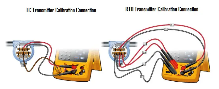
  1. Disconnect the process measurement sensor and connect the test connection wires in its place (Figure Left Side).
  2. Connect the mini-connector from the test wires to the TC source connection of the calibrator.
  3. Connect a DMM or other measurement tool to the tested device’s mA output.
  4. Verify the devices range or span. Apply the 0% value with the simulator and verify with the DMM that the output mA value or voltage is as expected.
  5. Repeat the test, applying the 50% and 100% temperature signals.
  6. If the measured output of the device is within limits, the test is complete. If not, adjust the device at zero (offset, 0%) and span (gain, 100%).
  7. Repeat steps 4 and 5 and verify for a correct response.

To use an RTD simulator to test a device with an RTD input:

  1. Connect the calibrator to the device input as shown in figure rigth side.
  2. Connect the calibrator output with the right combination to match the device configuration (2, 3 or 4-wire).
  3. Use the test procedure at left for thermocouple testing, starting at step 3.

Article source: Fluke
Don't Miss Our Updates
Be the first to get exclusive content straight to your email.
We promise not to spam you. You can unsubscribe at any time.
Invalid email address
You've successfully subscribed !

Continue Reading

Free Download Thermocouple Calculator
What is RTD Sensitivity ?
Thermocouple Cold Junction Compensation
Temperature Switch Principle
What is a Probe Thermometer? How to Calibrate and Use it?
Temperature Sensor Failure
Share This Article
Facebook Whatsapp Whatsapp LinkedIn Copy Link
Share
2 Comments
  • Amit says:
    November 18, 2016 at 6:04 am

    Difference between grounding and ungrounding thermocouple ?

    Reply
    • Mary says:
      November 26, 2017 at 9:50 am

      Grouded = fastest response.

      Reply

Leave a Reply Cancel reply

Your email address will not be published. Required fields are marked *

Stay Connected

128.3kFollowersLike
69.1kFollowersFollow
210kSubscribersSubscribe
38kFollowersFollow

Categories

Explore More

What is a Three-wire RTD ?
Thermocouple Extension and Compensating Cables
Difference Between 2 wire RTD, 3 wire RTD, and 4 wire RTD’s
Spiral Bimetallic Thermometer Principle
How Does an Infrared Thermometer Work?
Basics of Temperature Switch
Interview Questions on Temperature Measurement
Skin Type Thermocouple

Keep Learning

Calculate Resistance from Temperature for RTD

RTD Calculator : Calculate Resistance from Temperature

Electrical Resistance Temperature Curves of RTD

Resistance Temperature Detectors (RTD) Construction

Temperature Measurement Objective Questions

Temperature Measurement Objective Questions

PTC NTC Thermistors Comparation

Thermistor Working Principle

Thermowell Wake Frequency Calculation

Thermowell Wake Frequency Calculation

RTD installed after the Orifice Plate

Why RTD installed after the Orifice Plate ?

Thermocouple Temperature Measurements Errors

Thermocouple Temperature Measurement Errors

Filled-bulb Temperature Measurement

Filled-bulb Temperature Sensors

Learn More

Feedforward with Dynamic Compensation - 3

Feedforward Control with Dynamic Compensation

Ground Rod

What is a Ground Rod?

peak of a chromatogram

Measuring Gases Concentration in Chromatograph

Redundant system communication cable

What is Interface Module in Siemens PLC?

Logic Gates and Truth tables

Logic Gates and Truth tables

HART Protocol and Fieldbus Interview Questions

HART Protocol and Fieldbus Interview Questions

Difference between RCCB and RCBO

Difference between RCCB and RCBO

Introduction to Schneider PLC

Different Types of Schneider PLC

Menu

  • About
  • Privacy Policy
  • Copyright

Quick Links

  • Learn PLC
  • Helping Hand
  • Part Time Job

YouTube Subscribe

Follow US
All rights reserved. Reproduction in whole or in part without written permission is prohibited.
Welcome Back!

Sign in to your account

Username or Email Address
Password

Lost your password?