Commissioning is the formal process of verifying and documenting that the installed field instruments and control systems comply with and perform in accordance with the design intent.
Commissioning should be identified as a specific activity requiring its own planning, scheduling, management, and monitoring during the design and construction process. A commissioning team should be assembled including representatives of all involved parties.
Those represented should include as a minimum:
- Project management
- Facility operations
- Design engineer
- General contractor
- Mechanical subcontractor
- Electrical subcontractor
- System integrator
- Installation subcontractor
- Major equipment vendors
- Reliability engineer
- Maintainance Engineers
- Field and Control room operators
- Technicians
- Supervisors and so on.
The roles and responsibilities of the various parties within the commissioning process may vary with the agency and the type of project. In some cases, an independent engineer may be brought in to coordinate and oversee the commissioning process. If an independent engineer is not used, the design engineer should be retained to oversee the commissioning process.
In either case, certain key components of the program that must be included for a successful outcome:
- A clear definition of the process and the parties’ roles and responsibilities (Commissioning Plan).
- Integration of commissioning activities into the overall project schedule.
- An organized system of commissioning documentation.
- Development of written testing and verification procedures for every critical aspect of system performance.
- Review of these procedures by all affected parties prior to testing.
- Clear definition prior to testing of the criteria for acceptance.
- Procedures for correction and retesting in the case of failure.

Factory Acceptance Test (FAT)
A factory acceptance test and demonstration should be required in which the controller(s), I/O, and HMI hardware and software are verified to the extent possible without the actual field devices.
FAT test should demonstrate the following:
- Simulation of all inputs
- Operation of all outputs with dummy load
- Loop operation
- Control sequences
- Network communications
- HMI screens, displays, and alarms
- Operator control functions
- Physical and information security measures
For example, PLC systems providing control of standby generators and paralleling switchgear should be factory tested with the switchgear to demonstrate the actual operation of the breakers and other controls with simulated utility and generator voltage and frequency sources.
Integrity Testing
Pneumatic lines should be pressure tested per ISA RP 7.1 and checked for obstructions. Electrical conductors should be tested for continuity and insulation resistance according to industry standards for their voltage ratings.
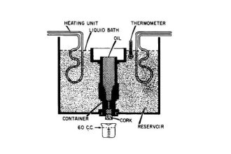
Calibration
Instrument and actuator calibration should be completed prior to the loop checkout or startup of systems.
The calibration program should include the following:
- All sensors, elements, indicators, transmitters, and actuators should be calibrated from NIST- traceable standards according to the manufacturer’s instructions.
- All calibration equipment should have current independent certification of accuracy.
- Stroke actuators and verify control action, limits, and end switches.
- Each calibrated instrument should be field-marked with a waterproof calibration tag bearing the range, setpoint, date and calibrator’s initials.
- An Instrument Certification sheet should be completed for each instrument and included in the system documentation.
- A Final Control Element Certification sheet should be completed for each control valve and included in the system documentation.
Instrumentation Documents
We need different types of documents that are used during instrumentation projects.
The below list shows some of the documents.
Instrument Functional Diagrams
Piping & Instrumentation (P&ID)
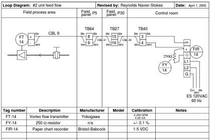
Loop Verification
The wiring of each control loop should be physically verified from the field device terminals to the controller.
Cable, conductor, terminal board and terminal designations should be verified and marked off as such on a copy of the loop diagram or equivalent schematic or wiring diagram. Verification should be by signal tracing, continuity verification, or “ringing out”.
Tags and labels placed during construction should not be considered adequate verification.
Each control loop should be verified by the injection of appropriate pressure, voltage, or current signal. Use actual signals where available.
- Closely observe controllers, recorders, alarm and trip units, remote setpoints, ratio systems, and other control components. Make corrections as required. Following any corrections, retest the loop as before.
- Stroke all control valves, cylinders, drives and connecting linkages from the local control station and from the control room operator interface.
- Check all interlocks to the maximum extent possible. In addition to any other as-recorded documents, record all setpoint and calibration changes on all system documentation.
All analog loops should be tuned for an optimum response using a closed-loop tuning method and the resulting gain, reset and rate recorded in the loop checkout sheet.
A Control Loop Checkout sheet should be completed for each loop.
Functional Performance Testing
Performance testing of all systems should be performed to verify compliance with the specified sequences of operations and control diagrams.
Functional performance testing consists of executing written step-by-step procedures in which a condition is initiated or simulated and the response of the system is noted and compared to the specified response.
Functional performance tests must verify the following:
- Manual and automatic control modes.
- Normal system conditions and modes of operation.
- Contingency conditions and modes of operation.
- Effect of all operator controls.
- Operation of all interlocks and permissives.
- Confirmation of failure state of all outputs.
- Physical and information security measures.
Software Integrity
It is common for PLC programming errors to be identified during functional performance testing of SCADA systems.
Typically these are easily corrected by revising the program logic via a laptop or computer and testing is then continued. It is also common for unforeseen circumstances to dictate that a change be made to the specified sequence of operation in the field, again easily implemented by changing the PLC logic.
These common startup processes contain the serious risk that a change made to correct misoperation at one point in the PLC control sequence may inadvertently affect the performance of other control sequences that have already been tested and accepted.
Re-commissioning
Whenever all or part of a SCADA system is modified, repaired or replaced, re-commissioning is required to verify that the portions of the system affected function correctly and that the work has not affected other portions of the system. The extent of re-commissioning required should be determined from the extent of the modifications.
For work that affects only devices and wiring external to the controller, the affected loops should be verified and functionally tested.
For changes to controller program logic or settings, the entire process or subsystem supported by that controller should be functionally tested, and the interface to the supervisory level HMI verified.
More extensive modifications may require re-commissioning of the complete SCADA system.
Functional performance testing for system certification must take place without operator intervention in the processor from beginning to end of the test. For this reason, it is highly recommended that a complete pre-test be conducted, using the full functional performance test procedure, prior to undertaking the certification test.
Instrument Certification Sheet
Prior to functional performance testing, all sensors and instruments should be calibrated and documented using an Instrument Certification Sheet or instrument checklist.
Each Instrument Certification Sheet should include four sections:
- Description of the Instrument such as Tag Number and Description;
- A table to record the calibration of Transmitters and Indicators;
- A table to record the calibration of Process Switches;
- A list of the Calibration equipment used.
Check the following instrumentation checklists:
- Transmitter Loop Checklist
- Process Switches Checklist
- PID Controller Checklist
- PLC Digital Input Checklist
- Instrument Installation Checklist
Instrument Description
The Instrument Description section should include the following information:
- Project name
- Project location
- Project number
- Certifier’s name
- Certification date
- Control loop number
- Drawing references (such as P&ID, wiring diagram, etc.)
- Instrument tag number
- Instrument Description
- Instrument location
- Instrument manufacturer
- Instrument model number
- Instrument serial number, if applicable
- Instrument range
- Instrument setpoint and deadband (for switches)
Transmitters Calibration
A record of the transmitters and indicators calibration should contain the following data for both increasing and decreasing input signals at 0, 25, 50, 75 and 100 percent of span.
- Input value
- Output value
- Error
Switches Calibration
A record of the process switches calibration should contain the following data for both increasing and decreasing inputs at all setpoints:
- Setpoint value
- Operate value
- Error
Calibration Equipment
The certification sheet should include the following information on the calibration equipment used.
- Type of Device
- Manufacturer and Model Number
- Accuracy
- NIST Traceability (Yes/No)
Definitions:
(1) Input: the process value
(2) Output: the measured value of the switch actuation point
(3) Span: the difference between the Maximum and Minimum value of the instrument
(4) Error: [(Output – Input) / Span] x 100%
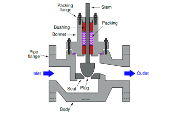
Final Control Element Certification Sheet
Valve actuators and other final control elements should also be calibrated and documented.
A final control element certification sheet should include four sections:
- Description of the final control element such as tag number and description
- A table to record the calibration of the I/P (current to pneumatic) converter, if applicable
- A table to record the calibration of the final control element
- A list of the calibration equipment used
Download: Control Valve Checklist
Final Control Element Description
The final control element description section should include the following information.
- Project Name
- Project Location
- Project Number
- Certifier’s Name
- Certification Date
- Control Loop Number
- Drawing References (such as P&ID, Wiring Diagram, etc.)
- Control Valve Tag Number
- Control Valve Description
- Control Valve Location
- Control Valve Manufacturer
- Control Valve Model Number
- Control Valve Serial Number, if applicable
- Control Valve Actuator (Pneumatic or Electric)
- Control Valve Positioner (Direct or Reverse), if applicable
- Control Valve Positioner Input and Output Signal, if applicable
- Control Valve I/P Converter Input and Output Signal, if applicable
- Control Valve Failure Mode (open or close) on air failure, if applicable
- Control Valve Failure Mode (open or close) on power failure, if applicable
Calibration of I/P Converter
A record of the I/P (current to pneumatic) converter calibration should contain the following data for both increasing and decreasing inputs at 0, 25, 50, 75 and 100 percent of span:
- Input value
- Output value
- Error
Calibration of Control Valve
A record of the final control element calibration should contain the following data for both increasing and decreasing signals at 0, 25, 50, 75 and 100 percent span:
- Input value
- Output travel (position)
- Error
Read: Valve Calibration Procedure
Certification of Calibration Equipment
The certification sheet should include the following information on the calibration equipment used.
- Type of Device
- Manufacturer and Model Number
- Accuracy
- NIST Traceability (Yes/No)
Definitions:
(1) Input: the control signal from the controller (PLC)
(2) Output: the measured value of the valve controller to the valve
(3) Travel: the valve percent open (not all valves are linear)
(4) Error: [(Output – Input) / Span] x 100%
Control Loop Checkout Sheet
The control system integrator should perform loop checkouts for each control loop in the system and provide suitable documentation certifying that the loop is tuned and operating properly.
The control loop checkout sheet should have a section verifying each of the six steps described below. When this has been verified and signed off, the functional performance testing (FPT) can be started.
Verify Mechanical Field Installation; that are no leaks;
- Motors and Pumps
- Valves and Dampers
Verify that all instruments are calibrated correctly for the specified ranges and setpoints;
- Pressure instruments
- Flow instruments
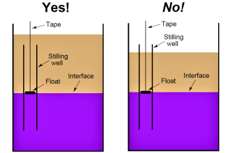
- Level instruments
- Temperature instruments
- Analysis instruments
Verify Electrical power wiring;
- Incoming power sources for proper voltage
- Field cables properly installed and identified
- Circuit breakers sized and operating correctly
- Fuses sized correctly inside control panels
Verify control system Input and Output wiring;
- Digital (switch) inputs
- Digital (on/off) outputs
- Analog (transmitters) inputs
- Analog (VFD’s, valves, and meters) outputs
Verify software logic is complete;
- Correct programs are loaded
- Factory Acceptance Test (FAT) thoroughly completed
- Software Management Practices in place
Verify HMI (or OIT) points and displays are complete;
- Graphic screens and screen navigation
- Alarm screens and operator actions
- Trend Displays and Data Archiving configured properly
The software logic and HMI/OIT should have been verified during the factory acceptance test.
The Control Loop Checkout Sheet should have a section verifying each of the steps described above. When this has been verified and signed off, the Functional Performance Testing can be started.
Join the Discussion
Share & leave us some comments on what you think about this topic or if you like to add something.


I really like this program. It open my mind. All those definition well explained.
It’s very helpful for Instrumentation Engineers.
Could you please make another detailed about biomedical instrumentation.
It’s very helpfull
Thank you for well information
Hello Gents,
Hello,
Having a valve on the NKOSSA site with a Fisher brand DVC6200 HC positioner, can you tell us how to set the valve position feedback please?
NB :Thanks for your feedback.
its really very good to refresh knowledge
How to energized the panel is it instrument technician question?