Modbus is a granddaddy of industrial communication protocols. Modbus is Modicon plus fieldbus.
Modbus, a serial communication protocol developed by Modicon in 1979. It is developed by Modicon for PLC in industrial applications, now it an open protocol. It is used over serial and Ethernet cable.
It is easy to implement and also easy to use. The term Modbus typically refers to one of three variants.
- Modbus ASCII.
- Modbus RTU
- Modbus TCP/IP.
Modbus RTU:
This is used in serial communication. Makes use of compact, binary representation of data for protocol communication.
Modbus ASCII:
This is used in serial communication, makes use of ASCII characters for protocol communication.
Modbus TCP/IP:
This is used for communication over TCP/IP networks.
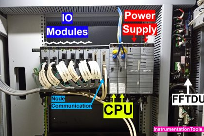
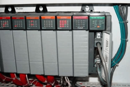
Modbus is often used to connect the supervisory computer with an RTU in the SCADA system.
Modbus
Modbus RTU is the most popular protocol, use three physical media.
- RS 232,
- RS 485,
- RS422.
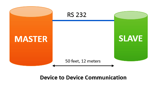
Point to Point Communication
RS 232 is a point to point communication. One device to one device can be connected and the distance between two devices is 50 feet (15 meters) then RS 232 does the job.
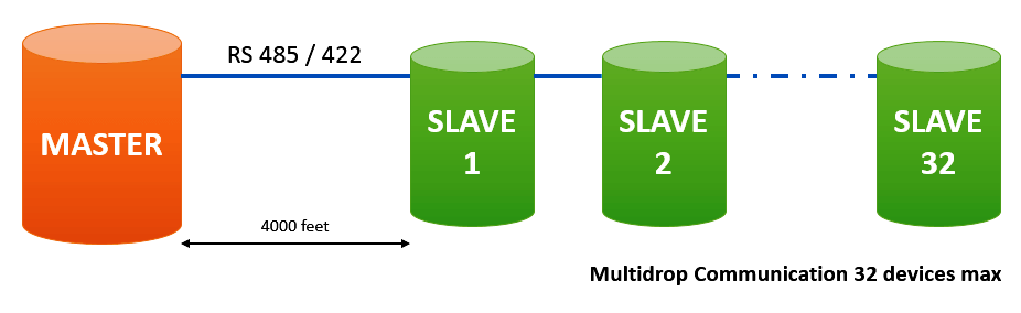
Multidrop Communication
To connect more devices on the same line, and have a distance greater than 50 feet, one can use RS 485, or RS422. This standard supports 32 nodes over 4000 feet( roughly 1200 meters).
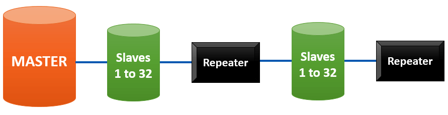
With Repeaters
Modbus is a simple Master/Slave protocol. With one being the master all are slaves only. Maximum of 32 slaves without repeaters on RS 485 physical medium.
With repeaters, 247 slaves can be connected as shown in the below figure.
They answer only when a master’s talk to them. If the master doesn’t talk they keep idle. There is also no requirement for diagnostic information on the slave’s health.
Modbus ASCII and RTU use physical layer RS232 or RS 485. A device configured in ASCII mode can not be used in RTU. Both are not compatible with each other.
Daisy Chain Network
Modbus and PROFIBUS are protocols built on RS 485, they used daisy chain architecture for connection.

RS 232 is a point to point communication,
RS 485 or RS 422 is for multidrop applications.
Profibus
PROFIBUS is a young athlete, lean and fast. As with the Modbus, there are a number of variants associated with Profibus.
- PROFIBUS PA,
- PROFIBUS DP,
- PROFIBUS FM
- PROFINET,
- PROFISAFE.
Profibus ( Process Fieldbus) is one of the standards for field bus communication in automation technology.
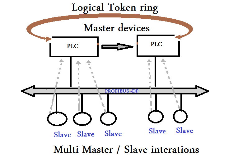
PROFIBUS is also a Master/Slave protocol. But with additional token ring protocol to allow multiple masters as shown in the figure below.
PROFIBUS has certain protocol features that let certain versions of it operate in multi-master on RS 485 which Modbus could be the only a single master.
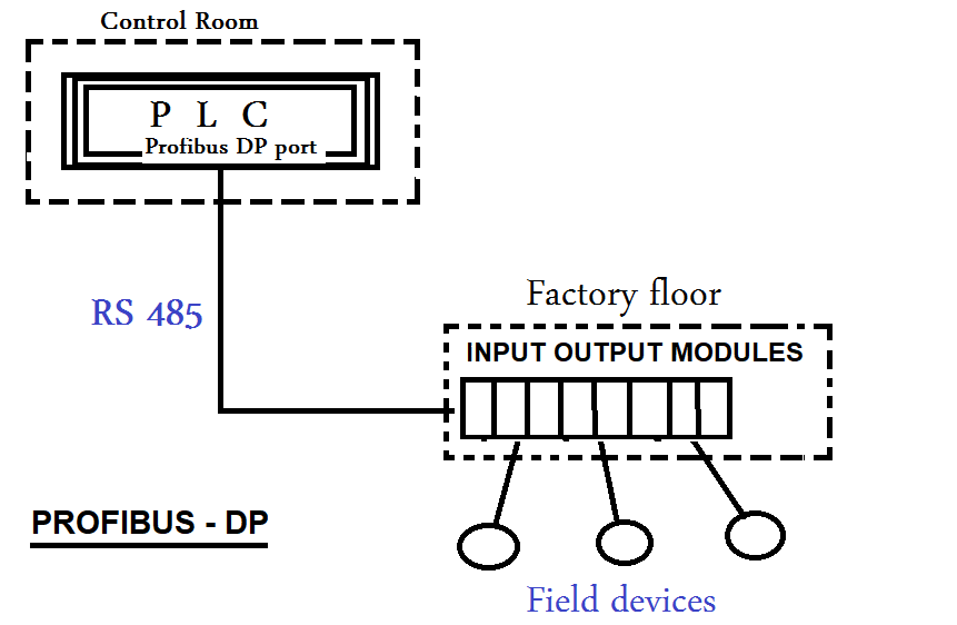
Profibus DP
PROFIBUS DP (DP-Decentralized Peripherals) is used in machine automation and other discrete signal applications.
The main physical layer for PROFIBUS DP is RS485.
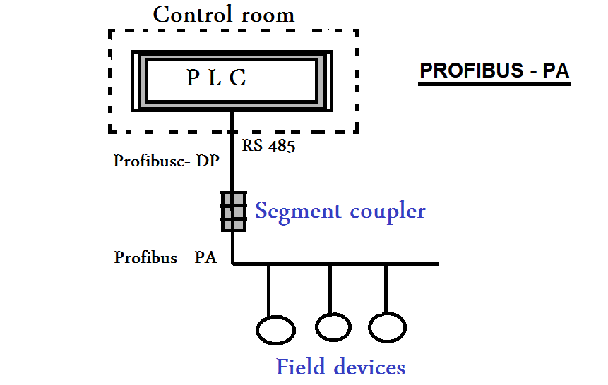
Profibus PA
PROFIBUS PA (PA- Process automation) is used in process control applications. It connects to PLC by Profibus-DP through a segment coupler as shown in the figure below.
PROFIBUS-PA devices are not directly accessible by PROFIBUS master, the segment coupler allows intrinsic connection to electrically isolate PA devices from DP network.
Foundation Fieldbus
Foundation Fieldbus: The idea behind field bus is to eliminate any point to point links between the field devices like transmitter, control valves and their controllers by a single digital connection.
Foundation Fieldbus technology is mostly used in process industries and power plants.
There are two variants.
Foundation Fieldbus H1
Foundation Fieldbus H1 is a bidirectional communication protocol with 3125 Kbits/S speed.
It utilizes twisted pair cable to connect field devices to the controller.
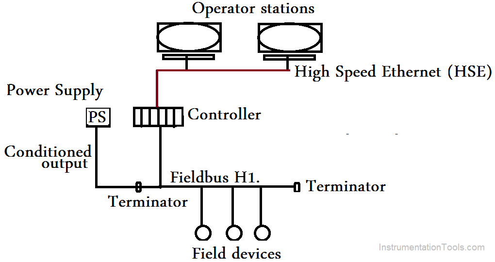
Foundation Fieldbus HSE
Foundation Fieldbus HSE. It utilizes Ethernet media to operate at 100/1000 Mbit for connecting gateways, host systems. Both FF H1 and FF HSE use different physical media and at different speeds.
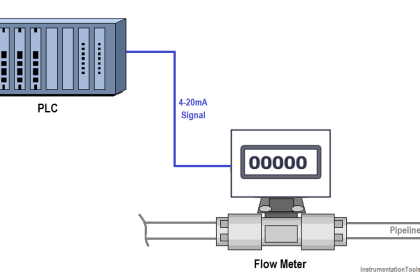
Foundation field bus was designed to address the needs of real-time process automation. FF was conceptually engineered as a replacement of the normal analog 4-20 mA current loop.
Foundation filed bus is not only a communication protocol but it is a language form for building control strategies.
FF is a peer to peer protocol. Field instruments such as transmitters can communicate with each other without a host e.g. A DCS or a PLC and they can initiate communication without a specific hos command.
The control functionality can be in the field devices or in the host (PLC or DCS) or partially in both.
When control functionality is within the field devices, without halting the loop, the host can be disconnected.
Also Read: HART Protocol versus Fieldbus
FF has a number of advantages making it a leading protocol for communicating field devices in digital closed-loop control.
For example, the separation between real-time and non-real time communications so that device management tasks do not interfere with closed-loop control.
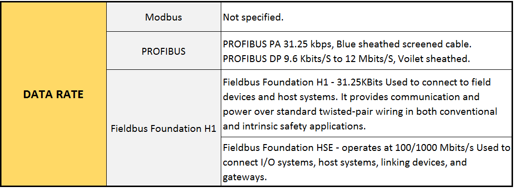
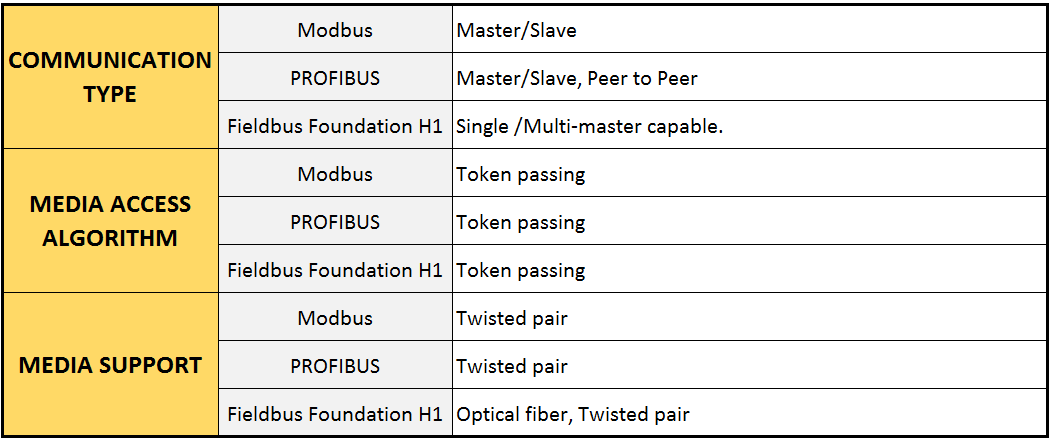
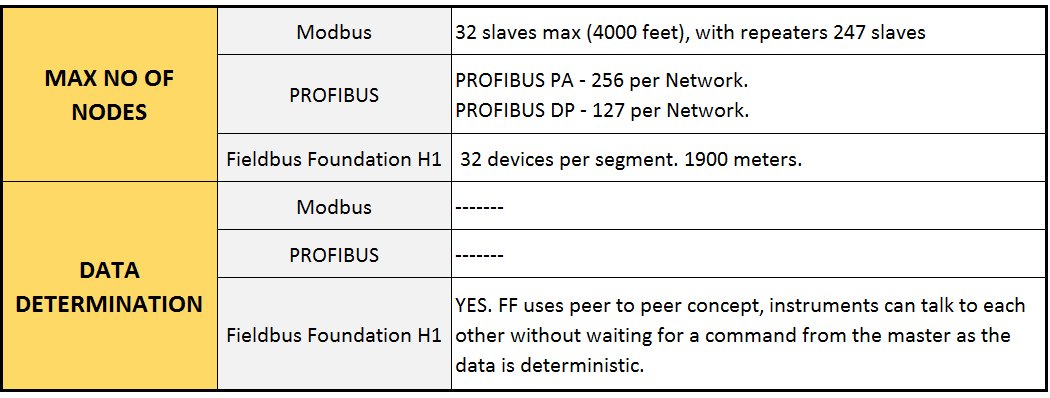
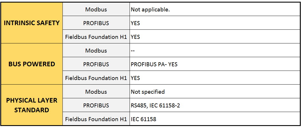
Compare Modbus, Fieldbus, and Profibus
If you liked this article, then please subscribe to our YouTube Channel for PLC and SCADA video tutorials.
You can also follow us on Facebook and Twitter to receive daily updates.
Read Next:
- What is Fieldbus?
- Automation Protocols
- What is HART Protocol?
- OSI Layers of Communication
- SCADA Communication
- Basic Industrial Networks


Superb explanation i ever read.
There is a requirement of Fieldbus, Module No PDP22-FBP-500
DC505 Connector Profibus DP/VI
Please suggest where to get. Any Contact No. Mailid . Please suggest.