The purpose of UPS is to provide regulated and uninterrupted single-phase / three-phase power supply within specified tolerances to critical loads during normal & emergency operations.
It provides backup power when utility power fails, either long enough for critical equipment to shut down safely or to keep required loads operational until a generator comes online.
Voltage surges or dips don’t damage sensitive electronics if they fed from UPS output.
Single Line Diagram of UPS System
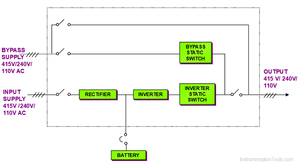
Main Components of UPS
Rectifier: Converts AC supply to DC Supply
Inverter: Converts DC Supply to AC Supply
Static Bypass Switch: Automatic / Manual transfer of load from the inverter to bypass supply. This will be imitated when Inverter fails, inverter output voltage fails, the input supply has some trouble.
Manual Bypass Switch: used to isolate any static transfer switch for maintenance or repair without interruption to UPS.
Battery Banks: When input supply fails, UPS will go into the discharge mode of batteries. These will give DC voltage to Inverter.
Modes of UPS
Normal mode: Input supply is converted to DC and Charging the batteries and inverter further converts to AC supply of desired output.
Discharge Mode: Input supply is not available. However, critical loads are fed from Batteries discharging and the inverter converts DC voltage to the desired AC supply output.
Failure mode: UPS is running though bypass input supply. Rectifier / Inverter and Batteries are not in operation.
This article mainly focuses on the sizing of UPS to arrive at correct and optimum UPS Sizing so that UPS is not so oversize or undersize.
UPS is generally rated in terms of VA (Volt Ampere) rating. It is available in various size (e.g. 300 VA to 5000 kVA)
Specification for UPS
Input Supply Voltage e.g. 3 phase, 415V ± 5%, 50Hz ± 2%
UPS Output Voltage e.g. 240 V ± 1% (Between P-N)
No of phases e.g. 1 Phase
Neutral: Grounded neutral
Output frequency e.g. 50 Hz ± 0.5%
Battery Autonomy (Battery Back up) e.g. 2 hr of ESD, FGS, and Telecommunication system, 30 min for DCS. This will decide the battery bank capacity (AH) and the number of batteries.
Crest Factor e.g. 3
Max single switching load e.g. 40 Ampere
Spare Capacity / Margin e.g. 20%.
UPS rating can be calculated based on downstream critical loads connected to UPS and their VA or Watt rating.
Watt = VA rating x Power factor
UPS Calculations
STEP 1:
List down all cabinets and loads of components or cabinet as a whole (VA or Watt).
The individual component that requires specific power (e.g. 110 VAC, 230 VAC, 24 VDC, 48V DC, etc) that can be fed directly from respective cabinets or power distribution panel or bulk power supply modules.
Control Panels
Control Panel related and other Auxiliaries loads but not limited to following
DCS, ESD, F&G (FGS) System and Marshalling cabinets
(TCS, TPS, BMS, BCS, BPS, TSI, Governor Panels, etc in case of the power plant)
- Controller nodes
- Modules/cards
- Bulk power supply (24V DC)
Solenoids, Hooters, Sounders, Beacons, Gas detectors, Flame detectors, LOS gas detectors, Buzzer, Annunciator, Relays, lamps, Earth leak monitors, I/H converters, Barriers, Isolators, HART Multiplexers, Wireless Gateways, etc
Interposing Relay Cabinets
- Bulk power supply
Relays used in IRP Cabinet which may be required for wetting the dry contact
Remote I/O Panels
(wherein RIO is connected to the controller via FO cable)
- Modules/ cards
- Bulk power supply (24V DC) – (Hooter, beacons, solenoids, media converters, etc)
- Ethernet switch and Firewall etc
Server Cabinets
- Cabinet rack-mounted Servers for different applications (Historian, OPC, Asset Management, Plant info Management, Cybersecurity, APC, OTS, Alarm management, rack type workstation of OWS / EWS, etc)
- Cabinet mounted HMI/Monitors, KVM Extender, KVM Switches
Network Cabinets
- Network Ethernet switches (Layer 2, Layer 3, etc)
- Firewalls, GPS, NTP Switches
- RS 485 to TCP/IP Convertors
Fiber optic patch panels
- Bulk Power Supply
Converters
Media converters (Fiber optic to Ethernet converters)
Package Systems
Packaged control panels: HIPPS, PLDS, CCS, PSA, HGP, N2 Gen, DM Water, HVAC, etc
- Components similar to DCS/ESD control panel and/ RIO
Vibration Monitoring Cabinets (MMS, CMS)
- Network Ethernet switch, Server, HMI, KVM components
- Vibration monitoring racks and isolators
Clean Agent Systems
- CO2 Flooding System
- Argonite systems
- Deluge System, etc.
Fire Alarm Control Panel
- CPU unit, Rack controller
- I/O Modules and communication modules
- Bulk power supply
Hooter, beacons, relays, other than addressable detectors
High Sensitivity Smoke detection
- Vesda Smoke detector panels e.g. VLS-304 / Power supply (VPS-220U)
Weather Monitoring
- Analyzer racks, HMI, printers, and media converters
- SOx, NOx, CO, SPM analyzer, Sampling system, heaters, smoke detectors, etc
- Wind speed, wind direction, Amb temp, Humidity, solar radiation, rain gauge sensor, and interface units, etc
Power Distribution Panel
Field Power distribution panels for field instruments but not limited to the following.
- Magnetic flowmeter
- Coriolis Flowmeter
- Ultrasonic Flowmeter
- Thermal Mass flowmeter
- Multiphase flowmeter
- Custody flowmeter, flow computers
- Analyzers (O2, Moisture, CO2, pH, Conductivity, CEMS, SWAS, etc)
- Conductivity type Level Switches
- Nucleonic level transmitters
- Stroke devices (used in chemical injection)
- Current to Hydraulic converter, Voith
- Flame Scanners
- Field Vibration monitors
- Reverse Rotation Switch
- Local control panel/field PLC Panel
- Emergency lighting e.g. exit gate lighting
Analyzer shelters
- GC,
- Sample handling system/pumps,
- Heat tracing, etc
Miscellaneous cabinets which require UPS supply
- Variable Frequency Drive Panels (VFD)
- Generator Control Panel
- Auxiliary panels like Generator Aux panels, Seal oil control panels
Telecommunication Systems
Telecommunication related loads but not limited to following
CCTV Cabinets
- Network Ethernet switch and servers
- Media converters, KVMs, HMI
- Storage drives, recording servers
- Outdoor cameras with washer units
- Large CCTV Displays (sometimes it is fed from utility supply)
PAGA Cabinets
- Bulk power supply (48V)
Loudspeaker controller, Beacon controller, Amplifier
- Network switch, Media converter, Ethernet switches, Baseband converter, etc
- Network controller, Call stations, Recorder, etc
Access Control Cabinets
- Bulk power supply (12V)
Access / Door controller, Badge reader, Electromagnetic lock, etc
- Media convertor, KVM, HMI
- Network Ethernet switch and servers
Telephone Systems Cabinets
- Call manager Servers, KVM & HMI
- Ethernet switches, IP Gateway and Analog Voice Gateways
- Main distribution frames, Intermediate distribution frames
Tetra Radio cabinets
- Base station
- Ethernet switches, servers, radio chargers, etc
- Transceiver, switching, control, and Gateway units
Workstation
Workstation related loads but not limited to following
1. Operator workstations, Engineering workstations, Packaged systems’ workstations, Telcom related workstations.
- Tower-type workstations (CPU)
2. Laptops
3. Printers and Fax machines: (sometimes these items are connected to the utility power supply), etc.
STEP 2:
Feeder location and redundancy requirement. It is important to know where the consumer is.
Sometimes UPS are kept at various buildings so that respective loads are fed from that UPS in the same building. When all consumers are at a nearby location then it is better to have common UPS in one place.
STEP 3:
Sum up all the UPS loads in the same area + same battery back up. Prepare the schematic drawings for load distribution.
e.g. identify all loads in the control room which requires 30 min UPS back up
e.g. identify all loads in substation which requires 2 hr UPS backup
e.g. identify all loads in the field which requires 30 min UPS Backup
Step 3 is not so important for UPS sizing but it is required for proper distribution and segregation of critical loads.
STEP 4:
It is important, to sum up, all loads in Watt or in VA rating then check it is possible to distribute with one UPS system or you may require a strategic location wise UPS system.
STEP 5:
Apply the load factor. Sometimes it is very much important to know those individual components are taken with the highest power consumption or operational power consumption.
It is not practical that all 100% of UPS loads are running at the same time. e.g. printers, fax, not all solenoids are activated; not all hooters, beacons are activated; not all annunciator activated all the time, an announcement on PAGA systems is not ON all the time, etc.
Hence it is advised to keep the load factor as 0.95 which means a 5% reduced UPS rating. This is a risk factor you are taking. (This step is optional)
STEP 6:
Apply gross spare/future capacity. This is the final step wherein you are getting the final rating which will be required.
STEP 7:
Based on the selected rating, you are advised to perform an adequacy check of UPS for the single largest load with crest factor. UPS shall be capable to handle the largest inrush current.
Tips
- Sometimes it is wise to kept field Power distribution panel (PDP) to cater all or maximum loads from field PDP. This will reduce the number of power cables going directly to each field consumers.
- Sometimes tender requirement calls for UPS supply requirement for some office or IT or administrative requirement within the plant area. These shall be identified and schematic drawing shall be prepared for distribution purposes.
- Always check that loose supplied items/ workstations/panels which require UPS Power are already listed down to arrive correct UPS sizing.
- It is also wise to consider 3 phase supply up to the Power distribution panel at the control room and Power distribution panel at the field. These places where you require maximum distribution. By considering 3 ph supply you will end up with a lower power cable size which also reduces efforts while cable laying.
- Miss-out of loads that require UPS supply, may have some diverse impact after-ward like an increase of UPS rating, an increase of battery banks, an increase of room size, or increase of building itself. It is very essential to review all the UPS Load requirement critically.
Author: Jatin Katrodiya
If you liked this article, then please subscribe to our YouTube Channel for PLC and SCADA video tutorials.
You can also follow us on Facebook and Twitter to receive daily updates.
Read Next:
- DCS and SIS System
- Calibration Frequency
- DCS Wiring Diagram
- Instrument Loop Test
- PLC, HMI, VFD Problem