The Loop checking is defined as pre-Commissioning activity which is initiated after installation of instruments in the field and carry out the instrument loop checks between installed field instrument and respective control system i.e. PLC or DCS.
What is Loop Checking?

Loop Check :
An operational check of the field, controller and HMI elements of a control loop. A Loop Check is intended to ensure the integrity of the following.
The field sensing device is properly installed in accordance with engineering specifications.
The field sensing device is calibrated in accordance with engineering specifications.
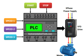
The field sensing device is properly connected to it’s communication path to the Distributive Control System Controller. (e.g. Current Loop, Multiple device Bus Communication Protocol, etc.)
The field sensing device develops and transmits a proper analogous signal in response to a variable impressed upon it or a simulation command issued to it.
The corresponding logic in the DCS Controller is ranged accordingly for the field sensing device analog and engineering units.
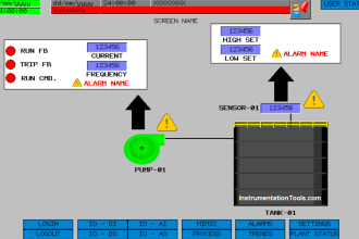
The HMI of the DCS Controller accurately displays the engineering unit response to the signal of the field sensing device.
Alarm points are properly entered into the logic of the DCS Controller and the HMI displays and logs these appropriately as they are reached.
Where control functionality is required, that the signal from the field sensing device is received by the control algorithm and generates the appropriate corrective output signal.
If present, the field control device, (e.g. Control Valve, Variable Speed Control etc.), is properly installed in accordance with engineering specifications.
The field control device is calibrated in accordance with engineering specifications.
The field sensing device is properly connected to it’s communication path to the Distributive Control System Controller. (e.g. Current Loop, Multiple device Bus Communication Protocol, etc.
The Field control device responds appropriately to the corrective signal received from the DCS Controller and that this action is appropriate to the desire process variable.
Where specified, the response action of the valve is correctly transmitted to the DCS Controller and displayed on the HMI.
SUMMARY
The Loop Check is intended to locate and identify deficiencies in the Field/Controller/HMI interface. This includes, but is not limited to, wiring and cabling issues, engineering issues and mechanical installation issues.
It is not the focus of the Loop Check to correct any deficiencies found. Full information concerning the deficiency is captured and passed on to the appropriate parties for correction. Minor corrections can be accepted, but this should be limited in scope.
Procedure:
A list of Loops is collected and identified by Tag Number.
Loops are grouped by Location, Availability, System, Equipment or other criteria. (Note: Locational Grouping of Loops results in the most efficient execution of Loop Check.
The field team can be routed in a logical geographical progression of one device to another adjacent device without time loss for accessing different floors, buildings, plant sections etc.
Loop availability can prevent this. If at all possible, Loop availability should be planned to accommodate Locational Grouping)
Each loop is assigned a separate unique folder.
Each Loop Folder is populated with either a comprehensive Loop Sheet, and/or individual elements, consisting of the following
- Field Device Tag Number
- Field Device Parameters
Calibrated Zero Process Value and corresponding Analog (common 4 ma)
Calibrated Full Process Value and corresponding Analog (common 20ma)
Action
Field Device Accessory List (e.g. Transmitter 3 Valve manifold, Valve Pneumatic Latch etc.)
Field Device Physical Location
Field Device instructions as appropriate
Field Device Wiring connection data. (Terminals, polarity)
Wiring Routing information (e.g. Junction Boxes, Terminals etc)
DCS I/O Marshalling Information, (Cabinet,Terminals, Polarity)
DCS I/O Card or Module information.
DCS Parameters
- Ranges
- Alarm points
DCS HMI Graphics assignments
From the Pending Loops file, the Console Engineer and the Field Technician draw the Loop Folders to be checked in that time period.
The Console Engineer (or Operator) and the Field Technician review the contents of each Loop Folder in the group to be checked, comparing parameters for parity and completeness of data.
A sequence of Check is agreed to the following
The Console Engineer prepares his record keeping tool, tracker, for the loops to be checked in the agreed upon sequence.
The Field Technician evaluates the test equipment to be used, collects same and proceeds to the first device to be checked.
The Field Technician communicates to the Console Engineer the Tag of the device he is at
The Console Engineer calls up the appropriate I/O channel
The Console Engineer calls up the appropriate HMI graphic or graphics
Transmitters
The Field Technician reviews the installation and process connections to ensure they are in accordance with the specification details and good installation practice.
Either by impressed signal, (“Pump Up”) or Communicator command, the Field Technician drives the transmitter output signal through it’s range. Slowing at Alarm Points so the Console Engineer can confirm alarm action.
(NOTE: Common is a 0% 25% 50% 75% 100% Check. This was originally necessary to confirm the linearity of earlier Pneumatic and ElectroMechanical devices, it no longer is as critical and becomes a matter of agreed upon preference.)
Any wiring and/or piping disturbed to accomplish signal impression is restored.
The Field Technician confirms the process connection line up is as desired. (e.g. For a Differential Flow Transmitter to be placed in service after check out, the three valve manifold would have the balance closed and the process ports open)
Control Loops
While the transmitter signal impression is occurring, the Console Engineer will call up the Control Algorithm faceplate and by placing the control mode (PID Controller) to Auto, determine that the output action is appropriate.
Control Valves
The Field Technician reviews the installation to ensure it is in accordance with the specification details and good installation practice.
If pneumatic, the Field Technician opens the air source checking for proper pressure adjustment and air quality.
If electric, the Field Technician energizes the proper breaker.
The Console Engineer adjusts the output signal to the valve while the Field Technician observes the action of the valve.
Jointly, the Field Technician and the Console Engineer determine if the resultant action is appropriate for the control signal sent and the previously determined action of the control algorithm.
Where present, the Console Engineer observes any feedback from the valve to be in agreement with the reported position of the valve action by the Field Technician.
Any accessories to the valve are checked for proper action.
We suggest you to check out the below articles on loop checks
Switches
The Field Technician reviews the installation to ensure it is in accordance with the specification details and good installation practice.
Either by Signal Impression, manual toggling, or conductor manipulation, the Field Technician causes a change in state of the field device signal.a
The Console Engineer observes the indication of the signal to be in agreement with the physical state as impressed on the device by the Field Technician.
The Console Engineer records the results of the results of the signal impression, alarm points, ranges, valve actions, etc.
If no deficiencies were noted during the Loop Check, the Loop Folder is placed in the Completed Loops File. At this point, the client signs for the Loop as being complete.
The Console Engineer records and captures any and all deficiencies noted by either the Field Technician or the Console Engineer on a sequential uniquely numbered form for each deficiency noted.
This deficiency form, or “Kick Back” is logged by the sequential number assigned to it in a Master Kick Back Log maintained by the Console Engineer
The Kick Back form shall include
- Tag number of the deficit device.
- Date
- Reporting Party
- Thorough description of the symptoms noted and any and all actions taken by the reporting party
Kick Back form is entered into the Active Kick Back file.
The Log Number of the Kick Back is noted in the Loop Folder and the Loop Folder is moved to the Detained Loops File.
The resolution team draws Kick Back forms from the Active Kick Back file.
Each time the deficiency is addressed, the Kick Back form is submitted to the Console Engineer.
The Kick Back shall include
- Date
- Resolving Party
- Thorough description of the corrective actions taken
- Recommendations for further actions
- Responsible party assigned to further actions
When the deficiency is corrected, the Kick Back form is submitted to the Console Engineer.
The Completed Kick Back shall include
- Date
- Resolving Party
- Thorough description of the corrective actions taken
If you liked this article, then please subscribe to our YouTube Channel for PLC and SCADA video tutorials.
You can also follow us on Facebook and Twitter to receive daily updates.
Read Next:


Loop check activity is checking entire loop functionality, from field to DCS or ESD or PLC or any logical system. It is necessary to check not only continuity of signal, but also range of calibration, alarms, set points and any signal included in the loop folder.
For DCS will be tested with HART communicator or temperature generator, 4-20mA, depends of witch instrument is involved.
For ESD (emergency shut down system) loop check will be done with proper instrumentation tools to produce the specific pressure or required level…
For valves you must check all signals as open, close, hi and low limit switch, reset buttons, hand switches , feedback must be check and a lot of other things must be checked .
Loops are direct, revers, split range … it is not easy and it is not only the continuity check to do.