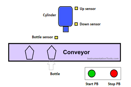
In this bottle-filling process PLC programming application, two sensors are used to control the Conveyor, Pump, and Linear actuator.
Note: This PLC logic example is an educational resource for the students to learn the basics of ladder logic.
Bottle Filling
Problem Statement:
Design a PLC ladder logic for the following application.
We are using two Push Buttons and two sensors to control the Conveyor, Pump, and Linear actuator.
The bottle-filling process which takes 15 seconds.
The Conveyor has a sensor that checks the bottle whether half-filled or fully-filled.
In case of fully-filled, the bottle will move on to the end of the first conveyor (that means the process is completed).
In the case of half-filled, a linear actuator is used to remove the bottle from the first conveyor and move it into the second conveyor so that it will go into the bottle-filling process again. This process takes 5 seconds.
PLC Automation Training
Instrumentation Tools provides the PLC automation training tutorials and courses on the Automation Community website.
This PLC program video explains the bottle-filling programming with simple steps.
Inputs and Outputs
Digital Inputs:
Start Push Button: I0.0
Filling Sensor: I0.1
Half Fill Sensor: I0.2
Stop Push Button: I0.3
Digital Outputs:
Conveyor: Q0.0
Pump: Q0.1
Linear Actuator: Q0.2
Applications of PLC Programming
Program Description
We have used Normally Open Contacts for Start Push Button(I0.0), Stop Push Button (I0.3), Filling Sensor (I0.1), Half Filled Sensor (I0.2) and Memory Bits.
We have used Normally Closed Contacts for Unlock Memory Bit 1 (M0), Pump (Q0.1) and Linear Actuator (Q0.2).
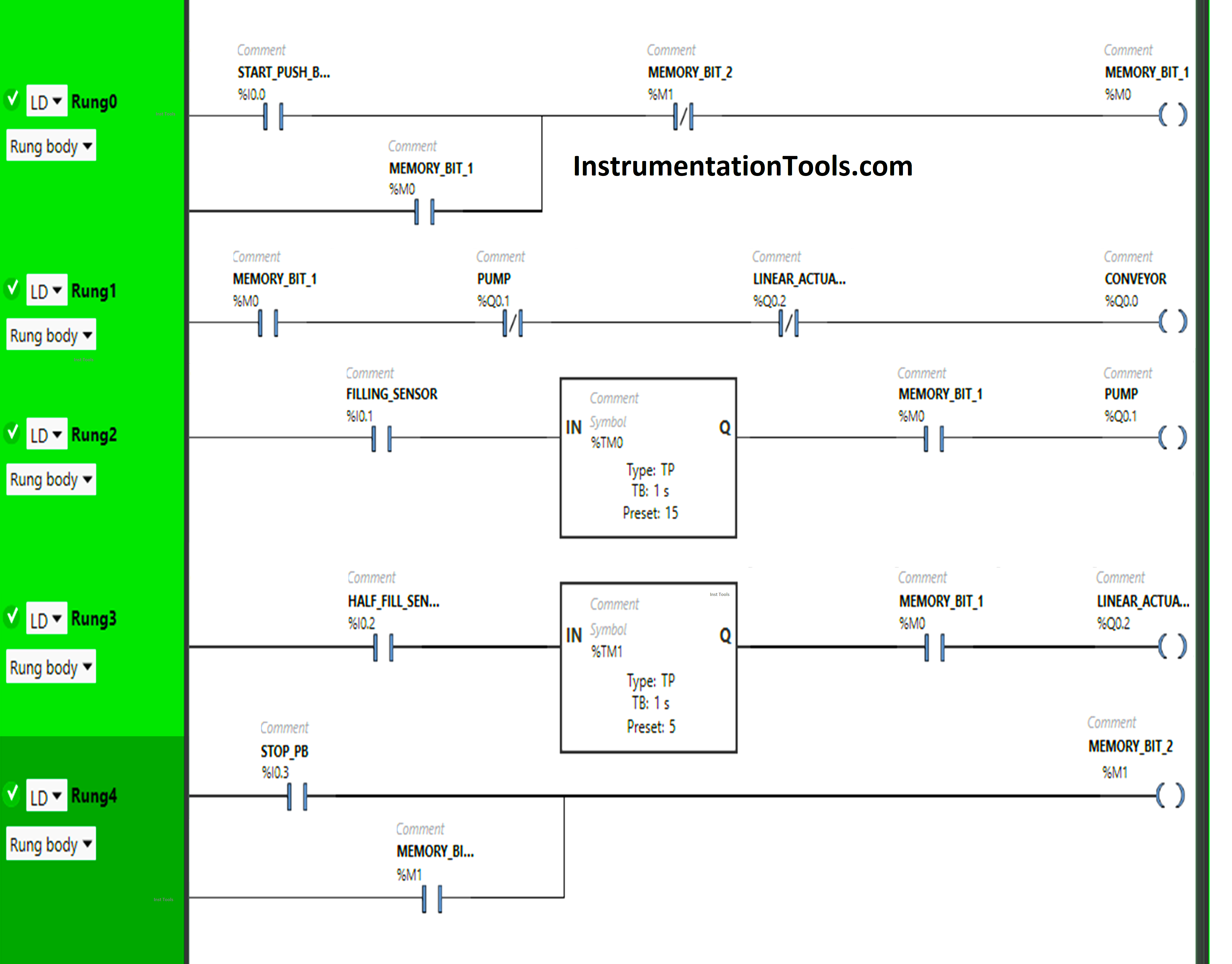
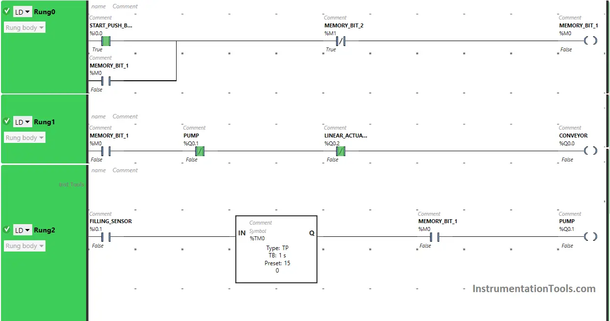
In Rung 0:
- Normally Open Contact is used for the Start Push Button(I0.0) to Turn ON Memory Bit 1 (M0).
- Normally Closed Contact is used for Memory Bit 2 (M1) to Turn OFF Memory Bit 1 (M0).
- Memory Bit 1 (M0) is latched so that when the Start Push Button(I0.0) turns OFF, Memory Bit 1 (M0) still remains ON.
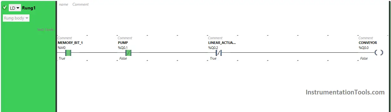
In Rung 1:
- Normally Open Contact is used for Memory Bit 1 (M0) to Turn ON the output Conveyor (Q0.0).
- Normally Closed Contacts are used for Pump (Q0.1) and Linear Actuator (Q0.2) to Turn OFF Memory Bit 2 (M1).
In Rung 2:
- Normally Open Contact is used for Filling Senor (I0.1) and Memory Bit 1 (M0) to Turn ON the output Pump (Q0.1).
- Timer Function Block type TP is used to Turn ON the output Pump (Q0.1) for a limited time.
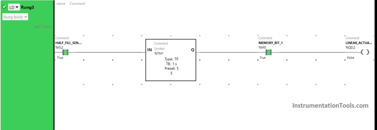
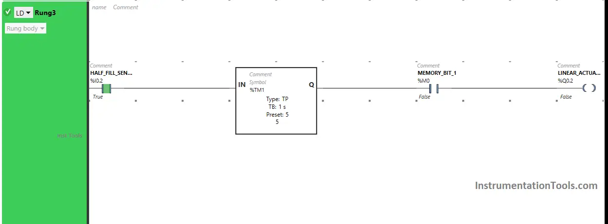
In Rung 3:
- Normally Open Contact is used for Half Fill Senor (I0.2) and Memory Bit 1 (M0) to Turn ON the output Linear Actuator (Q0.2).
- Timer Function Block type TP is used to Turn ON the output Linear Actuator (Q0.2) for a limited time.
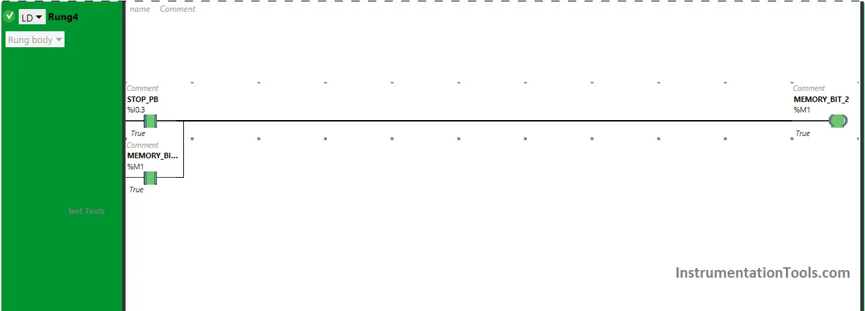
In Rung 4:
- Normally Open Contact is used for Stop Push Button (I0.3) to Turn ON Memory Bit 2 (M1).
- Memory Bit 2 (M1) is latched so that when the Stop Push Button (I0.3) turns OFF, Memory Bit 2 (M1) still remains ON.
Simulation Results
Now we simulate the PLC program and discuss the results. We may show the part of the logic instead of the complete program in the below test cases.
When the Start Push Button is pressed
When the Start Push Button (I0.0) is pressed, Memory Bit 1 (M0) turns ON as Normally Open Contact used for Start Push Button (I0.0) will be in True state and allows the signal to pass through it.
In a false state, Normally Closed Contact used for Memory Bit 2 (M1) also passes the signal to turn ON Memory Bit 1 (M0) and Memory Bit 1 (M0) turns ON and stores the data that the Start Push Button (I0.0) is pressed as Memory bits stores the data.
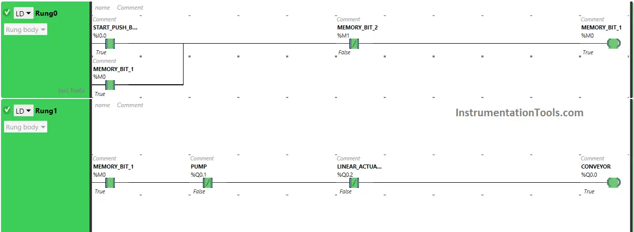
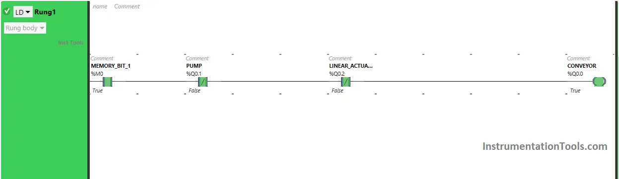
Memory Bit 1 (M0) is latched so that when the Start Push Button (I0.0) is released, Memory Bit 1 (M0) still remains ON. When Memory Bit 1 (M0) turns ON in Rung0, Normally open Contact used for Memory Bit 1 (M0) in Rung1 will be in a True state and pass the signal through it.
In a false state, Normally closed Contacts used for the Pump (Q0.1) and Linear Actuator (Q0.2) also pass the signal to turn ON the output Conveyor (Q0.0) and the output Conveyor (Q0.0) will turn ON.
When the Filling Sensor is activated
When Filling Sensor (I0.1) gets activated (Sensor detects bottle) and Memory Bit 1 (M0) is ON, the output Pump (Q0.1) turns ON as Normally Open Contacts used for Filling Sensor (I0.1) and Memory Bit 1 (M0) in Rung2 will be in True state and passes the signal to turn ON the output Pump (Q0.1).
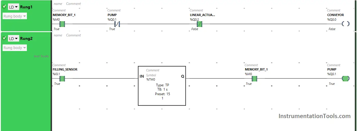
When the output Pump (Q0.1) turns ON in Rung2, Normally Closed Contact used for Pump (Q0.1) will be in True state and does not allow the signal to pass through it and the output Conveyor (Q0.0) turns OFF (Conveyor Stops).
The output Pump (Q0.1) will turn OFF after some time as Timer Function Block type TP is used to turn ON the output Pump (Q0.1) for a Limited time. The time is set to 15 seconds. After 15 seconds, the output Pump (Q0.1) will turn OFF.
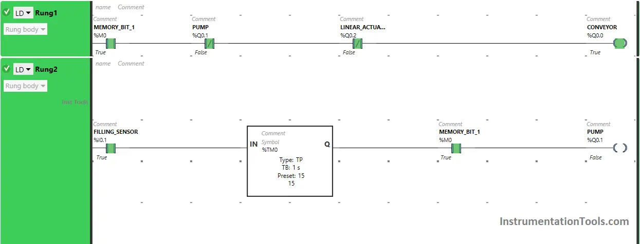
When the output Pump (Q0.1) turns OFF in Rung2, Normally Closed Contact used for Pump (Q0.1) will be in a false state and pass the signal through it and the output Conveyor (Q0.0) turns ON again (Conveyor turns ON again).
When Half Sensor Sensor gets activated
When Half Fill Sensor (I0.2) gets activated (Sensor detects bottle is half filled) and Memory Bit 1 (M0) is ON, the output Linear Actuator (Q0.2) turns ON as Normally Open Contacts used for Half Fill Sensor (I0.2) and Memory Bit 1 (M0) in Rung3 will be in True state and passes the signal to turn ON the output Linear Actuator (Q0.2).
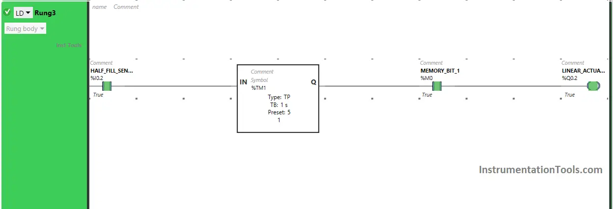
When the output Linear Actuator (Q0.2) turns ON in Rung3, Normally Closed Contact used for the Linear Actuator (Q0.2) will be in a True state and does not allow the signal to pass through it and the output Conveyor (Q0.0) turns OFF (Conveyor Stops).
The output Linear Actuator (Q0.2) will turn OFF after some time as Timer Function Block type TP is used to turn ON the output Linear Actuator (Q0.2) for Limited time.
The time is set to 5 seconds. After 5 seconds, the output Linear Actuator (Q0.2) will turn OFF.
When the output Linear Actuator (Q0.2) turns OFF in Rung3, Normally Closed Contact used for the Linear Actuator (Q0.2) will be in a false state and pass the signal through it, and the output Conveyor (Q0.0) turns ON again (Conveyor turns ON again).
When the Stop Push Button is pressed
When Stop Push Button (I0.3) is pressed, Memory Bit 2 (M1) turns ON and stores the data that Stop Push Button (I0.3) is pressed the first time as Memory bits stores the data.
Memory Bit 2 (M1) is latched so that when the Stop Push Button (I0.3) is released, Memory Bit 2 (M1) still remains ON.
When Memory Bit 2 (M1) turns ON in Rung4, Normally Closed Contact used for Memory Bit 2 (M1) in Rung0 will be in a True state and does not allow the signal to pass through it and Memory Bit 1 (M0) will turn OFF.
When Memory Bit 1 (M0) turns OFF in Rung0, Normally Open Contact used for Memory Bit 1 (M0) in Rung1, Rung2, and Rung3 will be in a false state and will not pass the signal through it and the outputs Conveyor (Q0.0), Pump (Q0.1) and Linear Actuator (Q0.2) will turn OFF and whole process stops.
If you liked this article, please subscribe to our YouTube Channel for PLC and SCADA video tutorials.
You can also follow us on Facebook and Twitter to receive daily updates.
Read Next:
- PLC Programming of Switch Program
- Quiz Program Logic using PLC Program
- Examples of SCADA and PLC Configuration
- PLC Programming with Sequencer Instruction
- PLC Program Motor Forward and Reverse