This is the PLC Program to implement SR flip flop in PLC. Learn the PLC programming with this example logic.
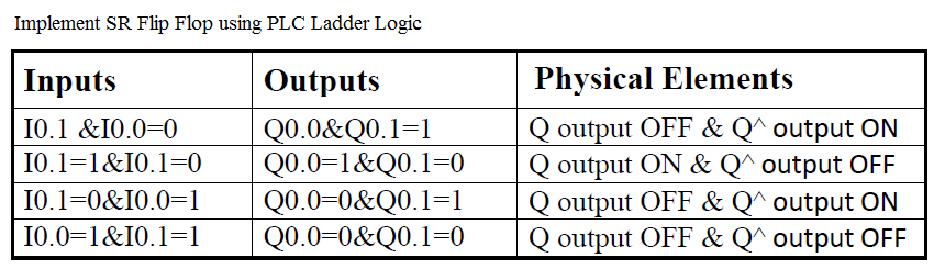
SR Flip Flop using PLC Ladder Logic
Problem Description
Implement a program for SR flip-flop logic in PLC using ladder language.
Problem Diagram

PLC Solution
As we know, more complex systems cannot be controlled with combinational logic alone. The main reason is that we cannot, or choose not to add sensors to detect all conditions. In these cases we can use event to estimate the condition of the system.
SR flip flop is used for Latch on or unlatch – to lock something ON or turn it OFF.
Most PLC has special instruction for SR flip flop function. so no custom logic required for such types of PLCs. SR flip flop first executes SET function and then RESET function.
Note :- Here we are considering simple function of SR flip flop instruction without using special instruction or using latch function. Here we are using simple latching circuit for SR flip flop function.

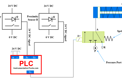
Here as shown in figure two push buttons or two inputs are taken for program implementation.
When user will press SET button or 1 is received at S input, Q output will be ON and if RESET button pressed or 1 received at R input, Q^ will be ON.
List of inputs/outputs
Digital Inputs
- Set Input :- I0.0
- Reset input :- I0.1
Digital Outputs
- Q output :- Q0.0
- Q^ output :- Q0.1
M memory
- Relay coil 1 :- M0.0
- Relay coil 2 :- M0.1
PLC Ladder Diagram to implement SR flip-flop

Program Explained
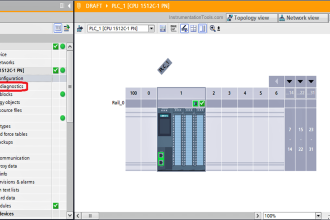
For this PLC program we use S7-300 PLC and TIA portal software for programming. We can implement this logic by using other PLC also.
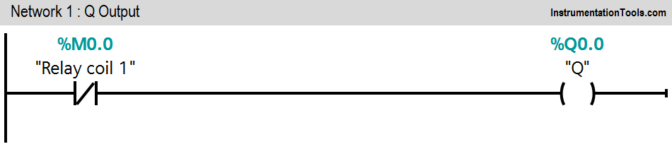
Network 1:
Here we used NC contact of relay coil 1(M0.0) so when reset button is pressed, Q output (Q0.0) is OFF.
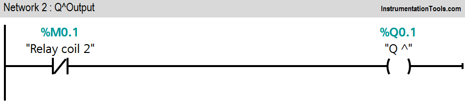
Network 2:
Here we used NC contact of relay coil 2 (M0.1) so when set button is pressed, Q^ output (Q0.1) is OFF.
Network 3:
Here when we press RESET button (I0.0), relay coil 1(M0.0) will be latched.
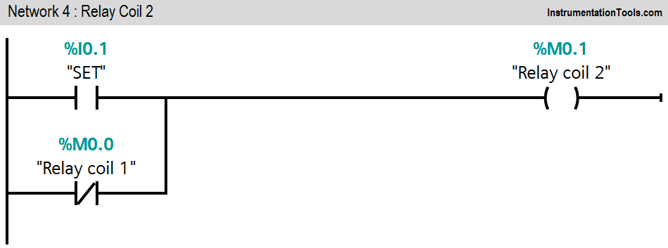
Network 4:
Here when we press SET button (I0.1), relay coil 2(M0.1) will be latched.
If both the inputs are low during power up, Q^ output (Q0.1) will go high because of its order. If both the inputs are
Note :- Above application may be different from actual application. This example is only for explanation purpose only. We can implement this logic in other PLC also. This is the simple concept of implementing SR flip function without instruction. we can use this concept in other examples also.
All parameters considered in example are for explanation purpose only, parameters may be different in actual applications.
Result
Author: Bhavesh
If you liked this article, then please subscribe to our YouTube Channel for PLC and SCADA video tutorials.
You can also follow us on Facebook and Twitter to receive daily updates.
Read Next:
- PLC Pneumatic Circuit Control
- Blinking Lamp on 5 Seconds Interval
- Entry and Exit Control of Car Parking
- Alarm Indication in Process Control
- Drain Same Products from Two Tanks