Write a PLC program where if the motor reverse direction push button (PB) is pressed, the motor stops for 3 seconds and reverse its direction. For instance, if the motor in clockwise (CW) operation and the counter-clockwise (CCW) push button (PB) is pressed, the motor is off for 3 seconds and then operates in the CCW direction, and vice versa.
Note the best practice to learn the PLC programming is to start writing the PLC program, take your time before you review the answer.
Inputs & Outputs:
I0.0: CW Push Button (Normally Open contact)
I0.1: CCW Push Button (Normally Open Contact)
I0.2: Stop Push Button (Normally Closed contact)
Q0.0: Motor CW
Q0.1: Motor CCW
T1: CW_delay timer
T2: CCW_delay timer
M0.0: marker 01 for negative edge detection
M0.1: marker 02 for negative edge detection
Timer during Motor Direction Change
Also Read: S_PEXT Instruction
PLC Program description:
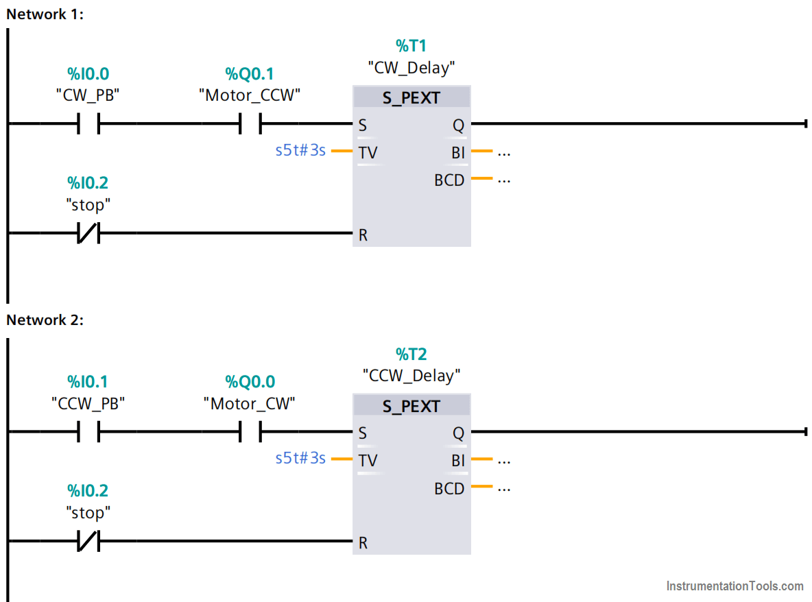
Network 01
- When the motor is in the CCW operation and the CW PB is pressed, the timer T1 is energized for 3 seconds.
- If the stop PB is pressed at any time the T1 is de-energized.
Network 02
- When the motor is in the CW operation and the CCW PB is pressed, the timer T2 is energized for 3 seconds.
- If the stop PB is pressed at any time the T2 is de-energized.
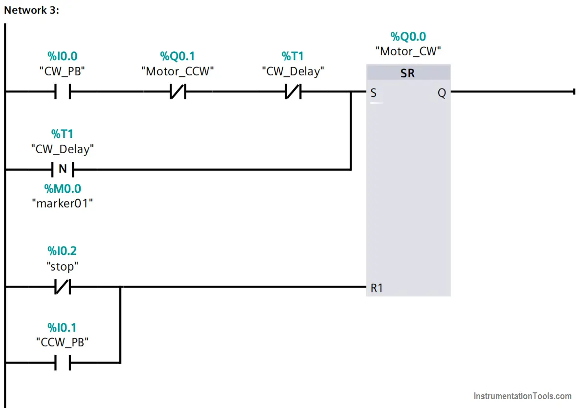
Network 03
- When the CW PB is pressed and the Motor CCW is not running and T1 is not energized, the set bit in the flip flop is energized.
- If T1 is energized, the negative edge would energize the set bit in the flip flop after 3 seconds when the T1 pulse fails to zero.
- When the stop PB is pressed, or the CCW PB is pressed, the reset bit in the flip flop is energized.
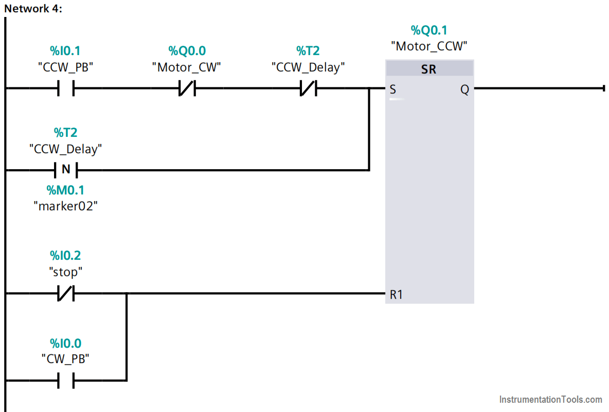
Network 04
- When the CCW PB is pressed and the Motor CW is not running and T2 is not energized, the set bit in the flip flop is energized.
- If T2 is energized, the negative edge would energize the set bit in the flip flop after 3 seconds when the T2 pulse fails to zero.
- When the stop PB is pressed, or the CW PB is pressed, the reset bit in the flip flop is energized.
Note: it’s very important to keep the order of the networks.
For instance, if you replaced network #01 with network #04 the program would not be executed properly as we need.
Conclusion
- In the begging, if any PB is pressed it should operate the motor in the dedicated operation.
- If the other direction PB is pressed this would de-energize the running direction and energize a pulse timer which is detected by a negative edge in the other direction flip flop.
Author: Karim Ali Anwar
If you liked this article, then please subscribe to our YouTube Channel for PLC and SCADA video tutorials.
You can also follow us on Facebook and Twitter to receive daily updates.
Read Next:
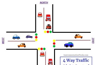
- 4 Way Traffic Light Control
- Extended Timer Logic in PLC
- Pulse Generation using PLC
- Jog Function in Motor Logic
- Latched Motor PLC Program