In this post, we will see the concept of high-speed inputs in a programmable logic controller (PLC).
PLC has a function of counter embedded in its software library. A counter is nothing but a function that counts things. For example, if we assign a sensor to a digital input of PLC.
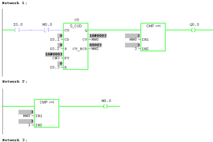
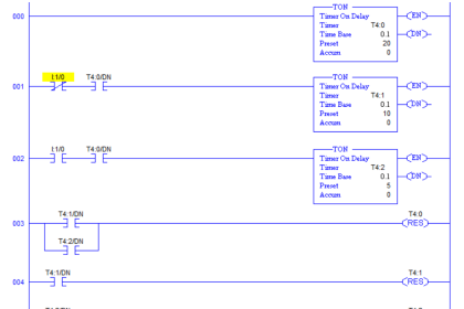
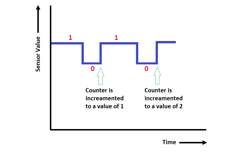
The counter is configured in the PLC to work as a step-up counter. That means, whenever the sensor changes a value, the counter will increment it’s value.
The counter is then programmed to count only positive-edge change (whenever the sensor goes from low to high, the counter will increment).
So, refer to the below image, the counter increments whenever the sensor at input changes from 0 to 1 (low to high). Thus, we get the number of times the sensor has been sensed by the PLC.
High-Speed Inputs in PLC
But, there are applications in PLC where input will change its value so fast that a normal counter of the type discussed will not be able to detect the change. This occurs because of the scan time of PLC execution.
A counter is written in a normal section of the PLC program and the section has a typical scan time of 5-10 milliseconds.
So, suppose if an input changes its state frequently within this time, then the counter will detect only some changes and thus, give a wrong value at the output.
Such types of devices are encoders, high-speed precision sensors, proximity sensors, laser sensors, etc.
High-Speed Counter (HSC)
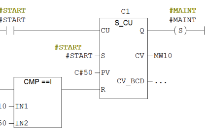
For this purpose, we have to use a high-speed counter (HSC) in PLC. A High-Speed Counter is a function that is used to count such high-speed inputs in a PLC.
So, suppose we have 16 digital inputs in a PLC CPU, 2-4 inputs that can be configured as high-speed inputs. That means you can connect such devices only to these inputs.
The wiring of a high speed input is categorised into two types – single phase and dual phase. Single phase means a single digital input will be used to increment or decrement the counter. Dual phase means two digital inputs will be used in combination to increment or decrement the counter.
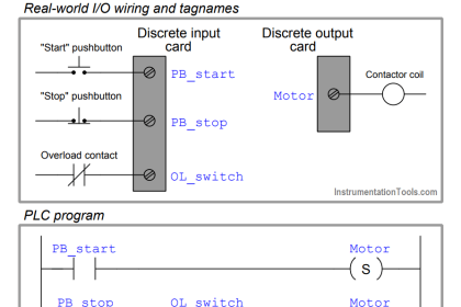
Consider a proximity sensor as an example of single-phase input. Every change of state (low to high) for that sensor on the digital input assigned will affect the counter.
A dual-phase input can be considered as an encoder (You can use the encoder as a single-phase input too).
An encoder has three-phase outputs from it. So, if one phase output of the encoder (A) is used to count in the forward direction and the other phase output (B) is used to count in the reverse direction, the counter in the PLC will work in that way. This means, if there is an input from A, then the counter will increment and if there is an input from B, then the counter will decrement.
Let us consider some configuration parameters in a high speed counter for more detailed information.
Selection of Input Type
As discussed earlier, it is used to select the type of wiring and configuration that will be done to work the counter accordingly.
Some of the most common modes used are – single-phase, A=Up and B=Down, A=Pulse and B=Direction, Normal Quadrature X1, Normal Quadrature X2, Normal Quadrature X4, Reverse Quadrature X1, Reverse Quadrature X2, Reverse Quadrature X4, etc.
Filter Time
The filter time determines the maximum counting frequency that will be taken by the counter. Typical values range from 0.002 ms to 4 ms (200 kHz to 100 Hz).
The PLC shows the corresponding maximum frequency for that. This means, suppose you select 0.002 ms and the frequency corresponding is 200 KHz.
The PLC will take a maximum of 200000 pulses per second from that digital input at a time. In short, it will take only one pulse per 0.002 ms interval.
So, indirectly, the frequency increases as time decreases. This improves the efficiency, avoids noise in the system and thus, reduces the effect of bounce on the input count.
Synchronize Input
A digital input can be configured to synchronize or reset the counter value. When the input assigned goes high from low, the counter is reset.
Enable Input
As the counter is counting high-speed pulses, there are occasions when even a slight movement of the device will increase the counter value to a great extent.
Suppose, you are using an encoder. An encoder must count the motion only when the system is running, and not when the system is in stop condition. If by chance, the encoder is moved by hand from someone, it will bring unwanted counts in PLC.
To avoid that, a digital input in PLC can be configured as an enable input. That means, the counter will take counts from the encoder only when there is high potential at this input or in simple terms, this input is high.
Threshold Value
Suppose you are using logic to initiate a system when the encoder has reached 10000 counts.
Now, if you use a normal comparator in the program to compare set value and encoder counts, the comparator will give an output after say 10500 counts. This happens due to PLC scan time.
A comparator is written in a normal PLC section. So, to bring accuracy, there is a provision to set the value in the high-speed counter itself. When the counter reaches 10000, then it will immediately give an output.
Reflex Output
As discussed earlier, based on a threshold value, the counter provides an output called reflex output.
You can program it in generally three ways – set reflex output if the count is less than a threshold; set reflex output if the count is between two threshold values or set reflex output if the count is more than a threshold value.
Due to these internal functions, you can achieve greater accuracy as the counter itself is doing all the functions. The reflex output can be a soft memory bit or a physical hardware digital output from PLC.
Counting Modes
This defines how the counter will function according to all the parameters set. The most general ones used are – one-shot, modulo loop, free large, event, frequency meter, etc.
All these parameters vary from PLC to PLC and each one of it as it’s working style.
Thus, a high-speed input is widely used in machine automation for achieving accuracy within a specified time; as mass production requires high output in a short span of time with maximum possible precision.
Author: Viral Nagda
If you liked this article, then please subscribe to our YouTube Channel for Instrumentation, Electrical, PLC and SCADA video tutorials.
You can also follow us on Facebook and Twitter to receive daily updates.
Read Next: