The PLC Sequencer Instruction (SQO) is an output instruction. SQO instructions can perform the same specific “ON” or “OFF” patterns of outputs that are continuously repeated.
The advantage of sequencer programming over the conventional program is the large savings of memory words.
Typically, the sequencer program can do in 20 words what a standard program does in 100 words. By setting up a sequence of events, sequencers make programming simpler and any future changes easier to make.
The sequencer output (SQO) instruction can be used to control output devices sequentially. The desired sequence of operation is stored in a data file or array, and this information is then transferred sequentially to the outputs.
PLC Sequencer Instruction

In the above block,we have six parameters
File :
Address of the reference sequencer file
Mask :
The address of the mask word or file through which the instruction moves data.
Dest :
Address of the output word or file for a SQO to which the instruction moves data from its sequencer file
Control :
Instruction’s address and control element (3 words) that stores the status byte of the instruction, the length of the file, and the position in the file.
Length :
Number of steps of the sequencer file starting at position 1.
Position :
The word location or step in the sequencer file from/to which the instruction moves data.
Refer the below Block,

Block Description :
On successive false-to-true transitions, the SQO instruction moves a step through the programmed sequencer file, transferring step data through a mask to a destination word.
The done bit is set when the last word of the sequencer file is transferred. On the next false-to-true transition, the instruction resets the position to step one.
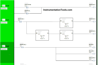
Let’s study the block using simple example,
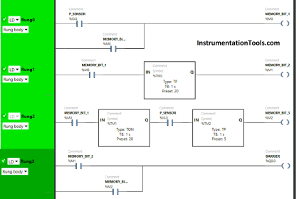
PLC Program

RUNG 0000
Start and stop PB with sequencer input switch is connected with sequencer output block.
Data file-Reference sequence file,
B3:0, B3:1, B3:2 & B3:3 are sets to 1 for reference,

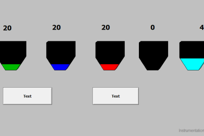
When Sequencer input I:0/2 turns ON for first time,
According to the reference file, O:0/1 turns ON.
Length is 4 & position is 1.

When Sequencer input I:0/2 turns ON for second time,
According to the reference file, O:0/2 turns ON.
Length is 4 & position is 2.

When Sequencer input I:0/2 turns ON for third time,
According to the reference file, O:0/3 turns ON.
Length is 4 & position is 3.

When Sequencer input I:0/2 turns ON for fourth time,
All outputs in the off condition.
Length is 4 & position is 4.
It s like reset, ready to start from beginning again.

Conclusion
We discussed the Sequencer block instruction in Allen Bradley PLC with example.
Author : Hema Sundaresan
If you liked this article, then please subscribe to our YouTube Channel for PLC and SCADA video tutorials.
You can also follow us on Facebook and Twitter to receive daily updates.
Read Next:


Respected Sir
Excellent material and knowledge base.
Can you give some examples for controlling servo valves of star hydraulics with 02coils connected in series
Thanks and Regards
Manoj Jhamb
email- Manoj. Powersolutions@gmail.com