Three levels of SCADA system architecture are recommended to support Industrial facilities. These vary in configuration to correspond to the size, criticality, and amount of mechanical and electrical equipment installed in the facility as noted.
NOTE : The below shown figures are only example configurations which are used in previous decades. Here shown only for reference. Modern configurations are quite easy and simplified.
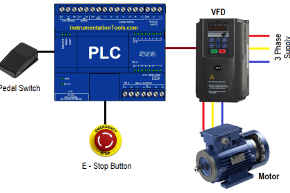
SCADA and PLC Configuration

Small PLC SCADA System
The small system is recommended to support a remote data and/or telephone switch site.
Such a facility would generally include a single service transformer and a single standby diesel generator. Some equipment inside would consist of a small rectifier for a 24 VDC bus, telemetry systems, PLC, HMI, cooling units
Systems for these facilities may not achieve the reliability/availability criteria specified for larger facilities. The level of SCADA system redundancy should reflect the mechanical/electrical system redundancy.
See below figure for a example scada configuration.

Medium PLC SCADA System
The medium system is recommended to support a main computer facility, which would include multiple service transformers and standby generators with paralleling switchgear, one or two large UPS systems, and multiple refrigeration machines with associated auxiliary equipment.
SCADA systems for this size facility should utilize redundant distributed control architecture. The level of PLC redundancy should be selected based on the design of the mechanical and electrical systems. Two options and suggested SCADA configurations are provided.
PLC SCADA System with Redundancy
The below figure presents a example SCADA configuration applicable to a facility with mechanical and electrical systems designed to provide redundancy through segregated systems.
In this case, PLCs controlling individual systems must have a reliability level adequate to maintain the required availability at the system they serve, but do not necessarily have to be redundant, as redundancy is provided through the N+X system approach. Failure of a single PLC will affect only the system it controls and the remaining systems continue to meet the mission-critical load.

SCADA Configuration
The below Figure presents a example SCADA configuration for a similarly sized facility in which mechanical and electrical systems utilize redundant components in a manifold configuration. In this design, any combination of components can be selected to serve the load.
This provides greater flexibility than segregating components into redundant systems, but requires common control of all components, making the PLC a potential single point of failure. In this configuration, system-level PLCs must have redundancy adequate to meet the required availability of the system.

Large PLC SCADA System
A large system serving a multi-facility site consisting of several installations will require a central supervisory control room networked to distributed control within the individual buildings appropriate to the mission and reliability criteria of each facility.
A control room will typically be located in each central power plant that is required for such a facility and the system can also be accessed from other locations distributed along the network. Redundant and segregated pathways are recommended for the on-site communication network. See below figure for a example configuration.

Reference : This material adapted from the “Department of the Army, TM 5-601, Supervisory Control and Data Acquisition (SCADA) Systems for Command, Control, Communications, Computer, Intelligence, Surveillance, and Reconnaissance (C4ISR) Facilities, 21 January 2006.”
If you liked this article, then please subscribe to our YouTube Channel for PLC and SCADA video tutorials.
You can also follow us on Facebook and Twitter to receive daily updates.
Read Next: