In this example, we will learn batch mixing with PLC ladder logic program using timer instructions such as TP, and TON.
Note: The ladder logic is dedicated to students to practice the PLC program with simple examples.
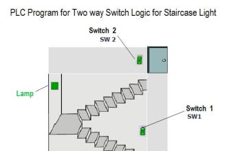
Batch Mixing
Problem Statement:
Design a PLC ladder logic for the following application.
We are using one toggle switch to control a Mixer and valve.
The MIXER runs for 10 seconds, and then a VALVE opens for 5 seconds, allowing ingredients to flow in.
After that the VALVE closes, and the MIXER runs for another 15 seconds.
PLC Logic Video Training
Get the PLC video training series from our YouTube channel and access hundreds of free example programs.
Inputs and Outputs
Digital Inputs:
Start Button: I0.0
Digital Outputs:
Mixer: Q0.0
Valve: Q0.1
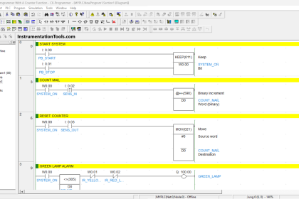
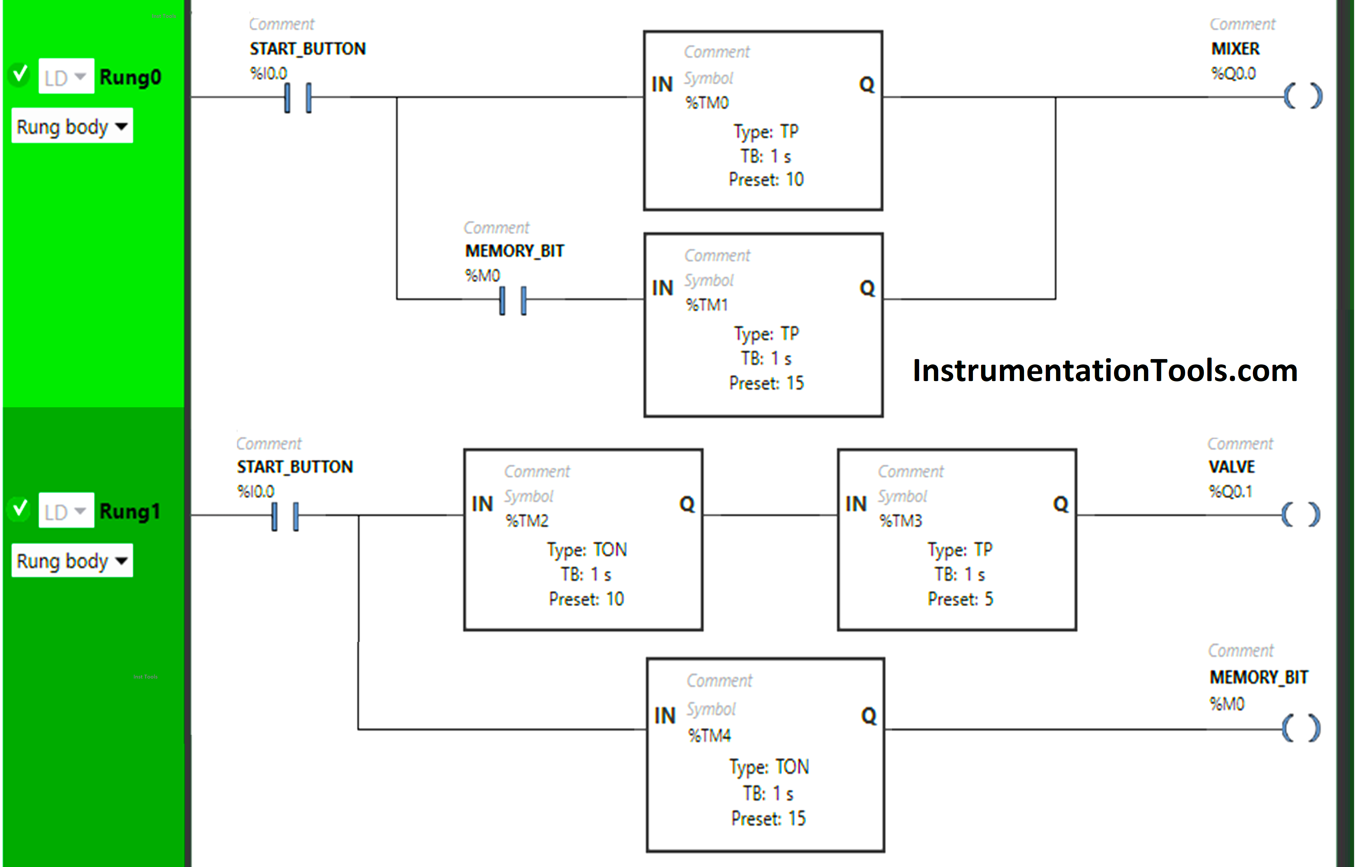
PLC Ladder Logic Program
Description
We have used Normally Open Contact for the Start Button (I0.0) and Memory Bit (M0).
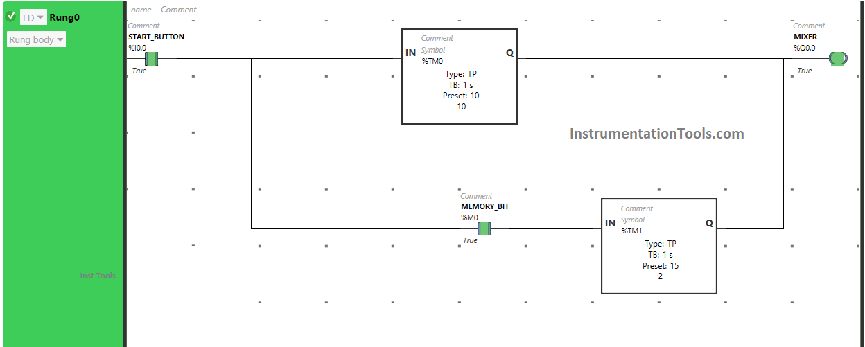
In Rung 0:
- Normally Open Contact is used for the Start Button (I0.0) and Memory Bit to Turn ON the output Mixer (Q0.0).
- Timer Function Block type TP is used to Turn ON the output Mixer (Q0.0) for a limited time.
- Time Function Block TON is used to delay the turning ON time of the output Mixer (Q0.0) for some time.
In Rung 1:
- Normally Open Contact is used for the Start Button (I0.0) to Turn ON the output Valve (Q0.1).
- Timer Function Block type TON is used to delay the turning ON time of the output valve (Q0.1) for some time.
- Timer Function Block type TP is used to Turn ON the output Valve(Q0.1) for a limited time.
- Timer Function Block type TON is used to delay the turning ON time of Memory Bit (M0) for some time.
Program Simulated
Here we simulate our PLC program. Note that we shown only the simulated part of the logic instead of the complete code. Watch the above video to understand the program.
Rung 0:
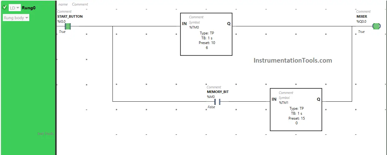
When the Start Button (I0.0) is turned ON, the Mixer immediately turns ON. Also, the Timer starts in Timer Function Block type TP Which turns ON the output Mixer (Q0.0) for a limited time. In this Timer Function Block, time is set to 10 seconds. So, after 10 seconds the output Mixer (Q0.0) will turn OFF.
Rung 1:
When the Start Button is turned ON, the Valve will turn ON after 10 seconds because the Timer Function Block type TON is used to delay the turning ON time of the output Valve (Q0.1), and the time is set to 10 seconds.
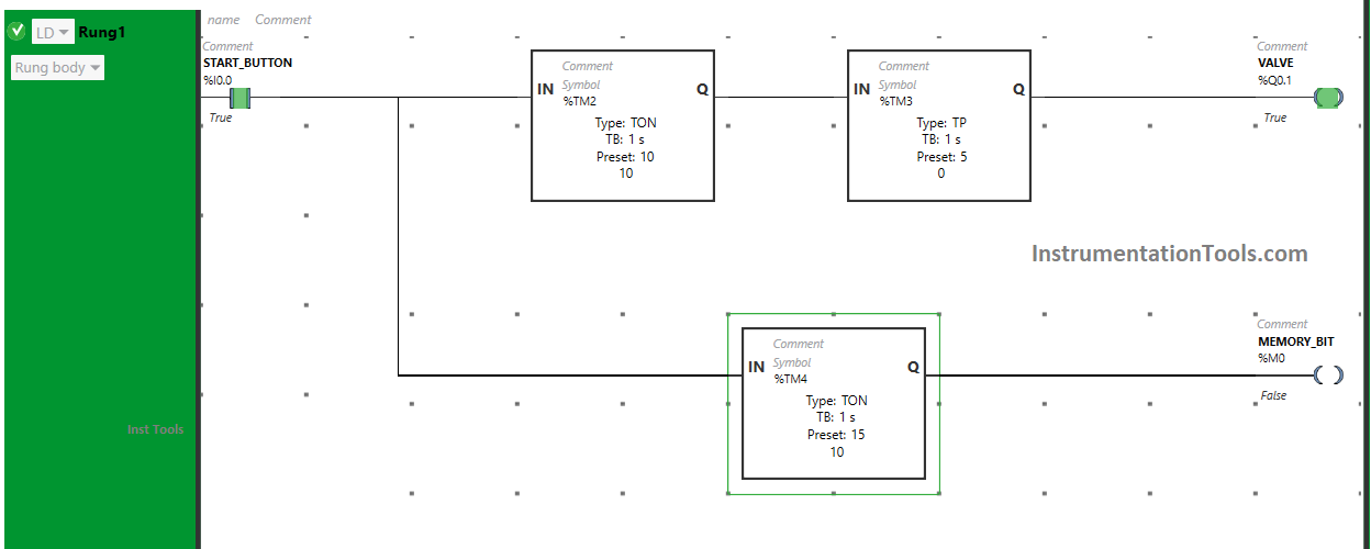
The output Valve (Q0.1) will remain ON only for 5 seconds as we have used Timer Function Block type TP to turn ON the output valve (Q0.1) only for a limited time and the time is set to 5 seconds. So after 5 seconds, the output Valve (Q0.1) will turn OFF.
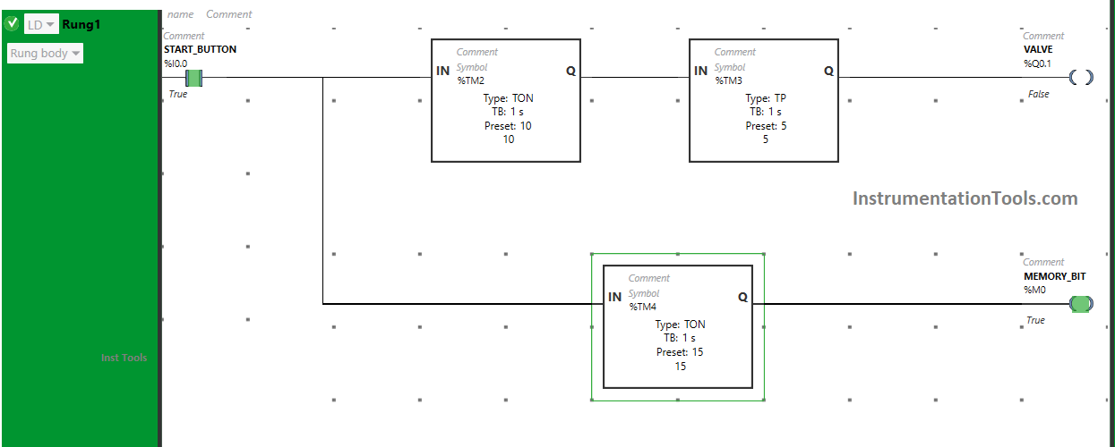
Also, When the Start Button (I0.0) is turned ON, the Memory Bit (M0) will turn ON after 15 seconds as we have used Time Function Block TON to delay the turning ON time of the Memory Bit and time is set to 15 seconds.
After 15 seconds, the Memory Bit will turn ON. When Memory Bit turns ON in Rung 1, it will turn ON Memory Bit in Rung 0 also and the output Mixer (Q0.0) will turn ON for 15 seconds as we have used timer function block type TP. So after 15 seconds, the output Mixer (Q0.0) will turn OFF.
If you liked this article, please subscribe to our YouTube Channel for PLC and SCADA video tutorials.
You can also follow us on Facebook and Twitter to receive daily updates.
Read Next:
- PLC Programming Example with Motor
- How to Blink Lights in Ladder Logic?
- Batch Simulator Program using LogixPro
- Pump Run for 10 seconds & OFF for 20 seconds
- Compare Batch Process and Continuous Process