Inst ToolsInst ToolsInst Tools
  • Courses
  • Automation
    • PLC
    • Control System
    • Safety System
    • Communication
    • Fire & Gas System
  • Instrumentation
    • Design
    • Pressure
    • Temperature
    • Flow
    • Level
    • Vibration
    • Analyzer
    • Control Valve
    • Switch
    • Calibration
    • Erection & Commissioning
  • Interview
    • Instrumentation
    • Electrical
    • Electronics
    • Practical
  • Q&A
    • Instrumentation
    • Control System
    • Electrical
    • Electronics
    • Analog Electronics
    • Digital Electronics
    • Power Electronics
    • Microprocessor
  • Request
Search
  • Books
  • Software
  • Projects
  • Process
  • Tools
  • Basics
  • Formula
  • Power Plant
  • Root Cause Analysis
  • Electrical Basics
  • Animation
  • Standards
  • 4-20 mA Course
  • Siemens PLC Course
Reading: PLC based Drink Dispenser System
Share
Font ResizerAa
Inst ToolsInst Tools
Font ResizerAa
  • Courses
  • Design
  • PLC
  • Interview
  • Control System
Search
  • Courses
  • Automation
    • PLC
    • Control System
    • Safety System
    • Communication
    • Fire & Gas System
  • Instrumentation
    • Design
    • Pressure
    • Temperature
    • Flow
    • Level
    • Vibration
    • Analyzer
    • Control Valve
    • Switch
    • Calibration
    • Erection & Commissioning
  • Interview
    • Instrumentation
    • Electrical
    • Electronics
    • Practical
  • Q&A
    • Instrumentation
    • Control System
    • Electrical
    • Electronics
    • Analog Electronics
    • Digital Electronics
    • Power Electronics
    • Microprocessor
  • Request
Follow US
All rights reserved. Reproduction in whole or in part without written permission is prohibited.
Inst Tools > Blog > PLC Tutorials > PLC based Drink Dispenser System

PLC based Drink Dispenser System

Last updated: March 4, 2021 2:13 pm
Editorial Staff
PLC Tutorials
4 Comments
Share
4 Min Read
SHARE

Develop ladder logic program for PLC-based Drink Dispenser System according to the logic given below,

Contents
PLC Dispenser SystemDispenser PLC ProgramProgram Description:Rung 1:Rung 2:Rung 3:Rung 4:Rung 5:Rung 6:Rung 7:Rung 8:
  1. Press the power button to activate the power supply as shown in the figure.
  2. Put manually glass (or a cup) on conveyor to hold up drink A/B/C as shown in the below figure.
  3. Press a one-button from A/B/C whatever you choose on the available types of drinks (It is toggle type switch).
  4. Press the start button from the local panel.
  5. The glass (or a cup) moves from limit switch 2 to 4 and stops the conveyor when glass reaches the appropriate limit switch, which we select from the A/B/C toggle switch.
  6. Glass (or a cup)  fill by drink A/B/C for 15 sec.(as per glass size) and conveyor again start-up to glass not reach limit switch -5.

PLC Dispenser System
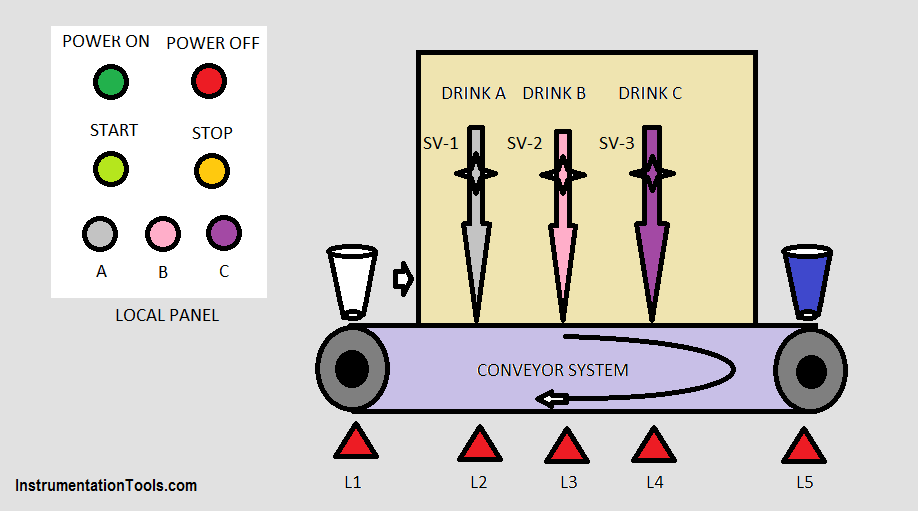
PLC based Drink Dispenser System

INPUTS:

  • I:0.0 – POWER ON PB
  • I:0.1 – POWER OFF PB
  • I:0.2 – START PB
  • I:0.3 – STOP PB
  • I:0.4 – LIMIT SWITCH, L1
  • I:0.5 – LIMIT SWITCH, L2
  • I:0.6 – LIMIT SWITCH, L3
  • I:0.7 – LIMIT SWITCH, L4
  • I: 0.8 – LIMIT SWITCH, L5
  • I:0.9 – SWITCH A
  • I:0.10 – SWITCH B
  • I:0.11 – SWITCH C

OUT PUTS:

  • 0:0.0 – POWER
  • 0:0.1 – CONVEYOR
  • 0:0.2 – SOV FOR DRINK A
  • 03- SOV FOR DRINK B
  • 0:0.4 – SOV FOR DRINK C

Dispenser PLC Program
PLC Dispenser System
Dispenser PLC program

Program Description:

Rung 1:

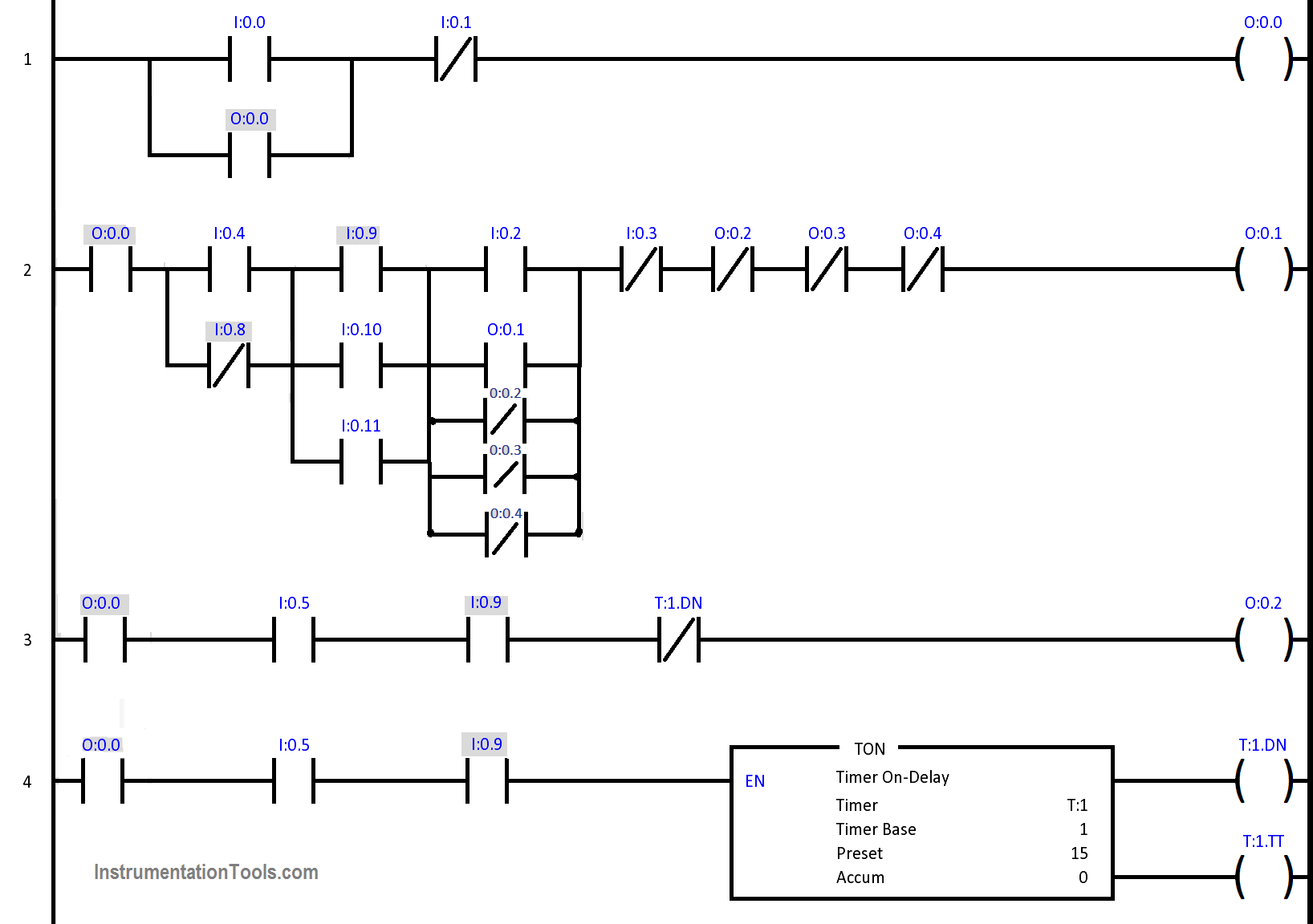
I: 0.0 and I: 0.1 respectively start and stop press button to control the power supply with latch output.

Rung 2:

Put the glass on L1 (I:0.4) place, which is converted from NO to NC, Press the Drink selection button from A/B/C, respectively enable I:0.9/I:0.10/I:0.11.

Press the Start PB to enable NC (I:0.2) to start the conveyor (O:0.1) until any solenoid valve (O:0.2/O:0.3/O:0.4) not energized and Stop PB(I:0.3) not enable.

After completion of the filling process, conveyor again starts until not reach up to L5 place (I:0.8).

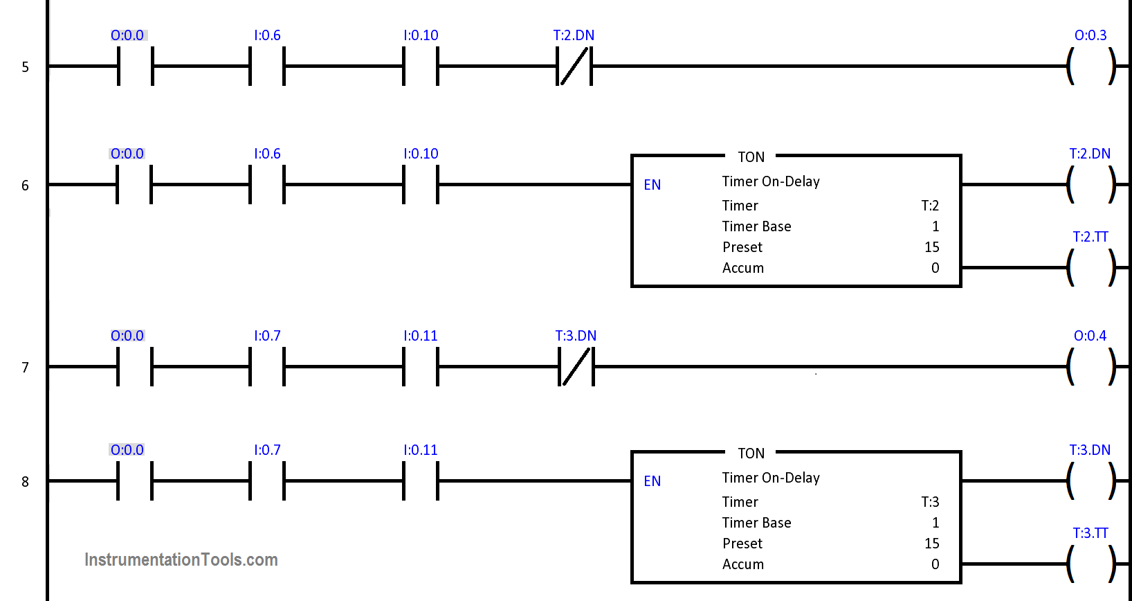
Rung 3:

Conveyor drives the glass up to L2 place as per selected drink type from A. enable the solenoid A (O:0.2) until timer (T:1.DN) bit not enable.

Rung 4:

Fill the drink A for 15 sec (assume constant as per glass size) start the Timer enable the SOV A up to 15 sec and respective timer down bit control the SOV ON/OFF (solenoid A (O:0.2)) state.

Rung 5:

Conveyor drives the glass up to L3 place as per selected drink type from B. enable the solenoid B (O:0.3) until timer (T:2.DN) bit not enable.

Rung 6:

Fill the drink B for 15 sec (assume constant as per glass size) start the Timer enable the SOV B up to 15 sec and respective timer down bit control the SOV ON/OFF (solenoid B (O:0.3)) state.

Rung 7:

Conveyor drives the glass up to L4 place as per selected drink type from C. enable the solenoid C (O:0.4) until timer (T:3.DN) bit not enable.

Rung 8:

Fill the drink C for 15 sec (assume constant as per glass size) start the Timer enable the SOV C up to 15 sec and respective timer down bit control the SOV ON/OFF (solenoid C (O:0.4)) state.

Author: Dhaval Maradiya

If you liked this article, then please subscribe to our YouTube Channel for PLC and SCADA video tutorials.

You can also follow us on Facebook and Twitter to receive daily updates.

Read Also:

  • Sequence Light Control in PLC
  • Valve Logic in Siemens PLC
  • PLC based Motor Logic Control
  • Industrial Automation PLC Example
  • Pump Running Hours using PLC
  • PLC Example using Limit Switch

Don't Miss Our Updates
Be the first to get exclusive content straight to your email.
We promise not to spam you. You can unsubscribe at any time.
Invalid email address
You've successfully subscribed !

Continue Reading

Types of Interrupt OB in Siemens Tia Portal
Drilling Process using PLC Program
MOVE Instruction in PLC – What You Need to Know?
Difference between DCS & PLC Systems
Standard Colors in PLC Automation Systems
Automatic Paper Cutting Machine Using CX-Programmer
Share This Article
Facebook Whatsapp Whatsapp LinkedIn Copy Link
Share
4 Comments
  • ajif says:
    October 22, 2019 at 3:13 pm

    what is the use for i:0:4 (L1)

    Reply
    • Tharun says:
      October 22, 2019 at 5:15 pm

      Limit Switch (L1) is used to detect the presense of empty glass or bottle.

      Reply
  • ajif says:
    October 23, 2019 at 3:29 pm

    what i mean, any toggle switch on (a, b, c ) conveyor will be on. then what is the use for L1 and start button ?

    Reply
  • Kapil Kumar says:
    June 21, 2020 at 12:11 pm

    Sir foundery moulding machine ka ladder logic bniya

    Reply

Leave a Reply Cancel reply

Your email address will not be published. Required fields are marked *

Stay Connected

128.3kFollowersLike
69.1kFollowersFollow
210kSubscribersSubscribe
38kFollowersFollow

Categories

Explore More

How to Password Protect HMI in Siemens TIA Portal?
Traffic Light Control using PLC Ladder Logic
PLC Pump Control: 10 seconds ON & 20 seconds OFF
What is a Data Block? Global Data Blocks in PLC
Example PLC Program
PLC Ladder Logic Example
Speed Control of Pneumatic Cylinder (Explanation with PLC)
Wet Contacts and Dry Contacts in PLC Systems

Keep Learning

PLC engineering software

How to Download GX Works? Mitsubishi PLC Software

Sorting PLC Program Simulation

Sorting & Distribution Line PLC Programming – Advanced Logic

PLC Program for Controlling Conveyors ON Sequence and OFF Sequence

PLC Program – Controls Conveyors ON and OFF Sequence

Connecting Faceplates to PLC Project

Connecting Faceplate to PLC Project – HMI Tutorial

Learn PLC Programming

Basics of Ladder Diagram in PLC Programming

Advantages of Redundant System

Redundant Automation Systems – Need and Advantages

plc-analog-signals-wiring-techniques

PLC Analog Signals Wiring Techniques

SCADA and HMI Systems - Differences, Similarities, Purpose

SCADA and HMI Systems – Differences, Similarities, Purpose

Learn More

Application of Feedback Objective Questions

Application of Feedback Objective Questions

Top 20 Service Business Opportunities in the Instrumentation Industry

Top 20 Instrumentation Service Business Opportunities in the Industry

Safety Relief Valve Material Selection

Measurement and Instrumentation Objective Questions

Measurements & Instrumentation Quiz – Set 5

Siemens micro memory card

Micro Memory Card (MMC) in Siemens PLC

Analyzers Questions and Answers

Analyzers Based on Gas Density Questions & Answers

BACNet Protocol

What is the BACNet Protocol? BACNet IP vs. BACNet MS/TP

How is pressure drop calculated through a valve?

How is Pressure Drop Calculated through a Valve ?

Menu

  • About
  • Privacy Policy
  • Copyright

Quick Links

  • Learn PLC
  • Helping Hand
  • Part Time Job

YouTube Subscribe

Follow US
All rights reserved. Reproduction in whole or in part without written permission is prohibited.
Welcome Back!

Sign in to your account

Username or Email Address
Password

Lost your password?