PLC program for fish feeding system to dispense the food if there is movement of fish in the pond for a defined time interval.
Note: This PLC exercise targets the engineers students and working professionals to learn the programming basics.
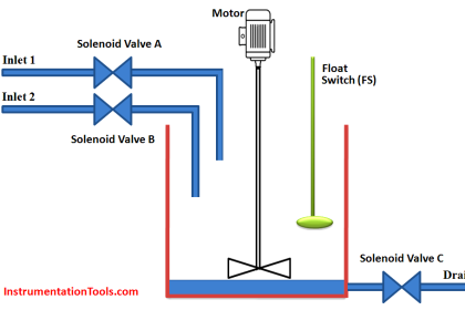
Fish Feeding System
Problem Statement:
Design a PLC ladder logic for the following application.
We are using one toggle switch and one sensor to control three valves.
The system should dispense three types of food for 5 seconds every 15 seconds. It will dispense food only if there is movement of fish in the nearby water.
Automation Academy
The automation community provides online free learning courses on PLC, SCADA, and HMI.
This PLC programming video explains the fish-feeding logic.
Inputs and Outputs
Digital Inputs:
Start Button: I0.0
Sensor: I0.1
Digital Outputs:
Valve 1: Q0.0
Valve 2: Q0.1
Valve 3: Q0.2
Ladder Logic
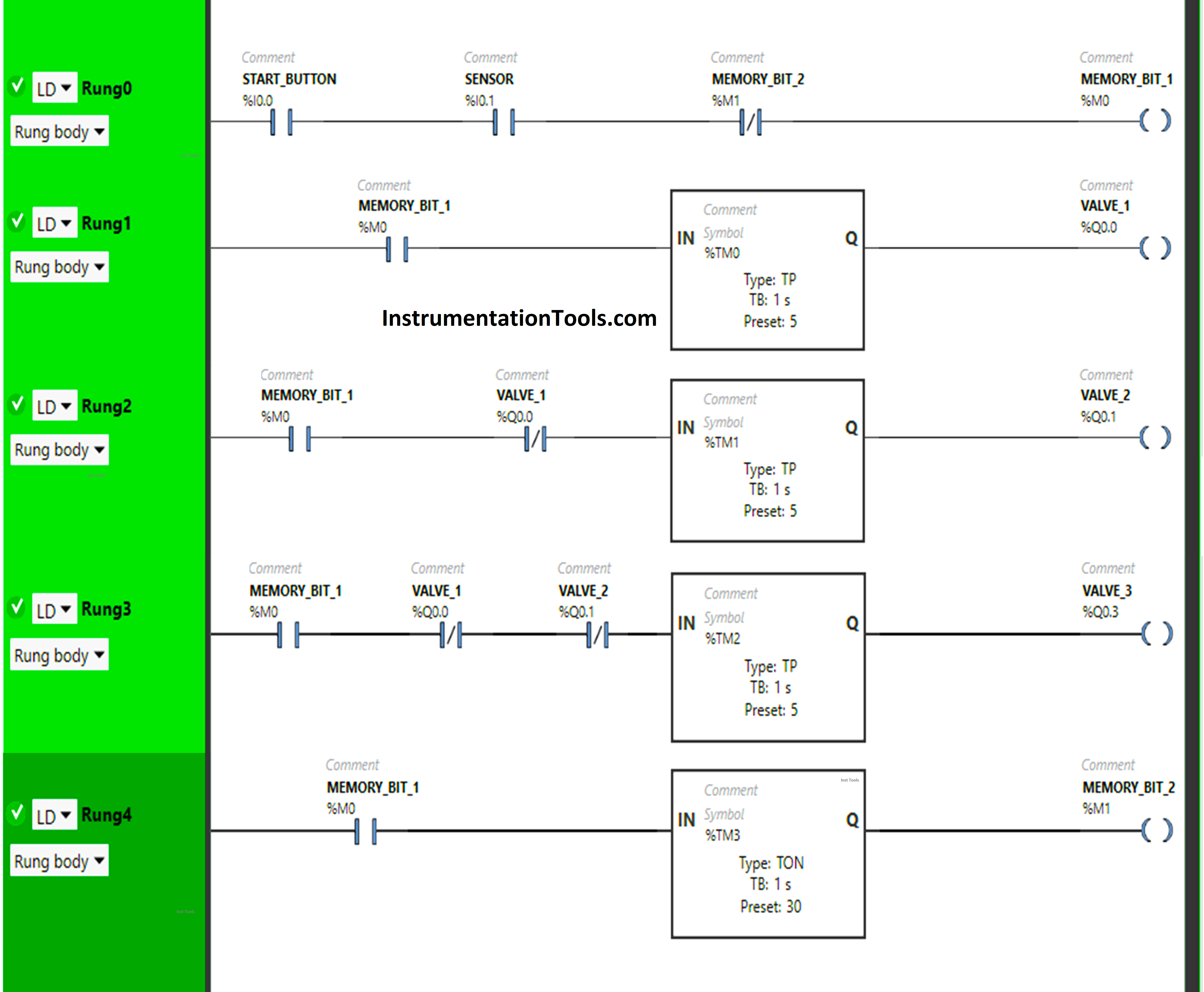
PLC Program Explained
We have used Normally Open Contacts for the Start Button (I0.0), Sensor (I0.1), and Memory Bit 1 (M0).
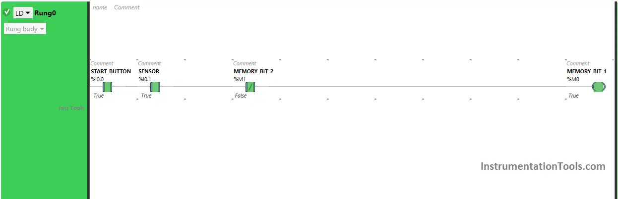
In Rung 0:
- Normally Open Contacts are used for the Start Button (I0.0) and Sensor (I0.1) to Turn ON Memory Bit 1 (M0).
- Normally Closed Contact is used for Memory Bit 2 (M1) to turn OFF Memory Bit 1 (M0).
In Rung 1:
- Normally Open Contact is used for Memory Bit 1 (M0) to Turn ON the output Valve 1 (Q0.0).
- Timer type TP is used to Turn ON the output Valve 1 (Q0.0) for a limited time.
In Rung 2:
- Normally Open Contact is used for Memory Bit 1 (M0) to Turn ON the output Valve 2 (Q0.1).
- Normally Closed Contact is used for Valve 1 (Q0.0) to turn ON the output Valve 2 (Q0.1).
- Timer type TP is used to Turn ON the output Valve 2 (Q0.0) for a limited time.
In Rung 3:
- Normally Open Contact is used for Memory Bit 1 (M0) to Turn ON the output Valve 3 (Q0.2).
- Normally Closed Contacts are used for Valve 1 (Q0.0) and Valve 2 (Q0.1) to turn ON the output Valve 3 (Q0.2).
- Timer Function Block type TP is used to Turn ON the output Valve 3 (Q0.2) for a limited time.
In Rung 4:
- Normally Open Contact is used for Memory Bit 1 (M0) to Turn ON Memory Bit 2 (M1).
- Timer Function Block type TON is used to delay the turning ON time of Memory Bit 2 (M1) for some time.
Simulation Results
Let’s simulate the PLC program and analyze the results. Please note that we may show only the part of the logic instead of the complete program in the below test cases. We recommend you to watch the above given PLC video.
Rung 0:
When Start Button (I0.0) is turned ON and Sensor (I0.1) gets activated (Sensor detects Fishes), Memory Bit 1 (M0) turns ON as Normally Open Contact used for Start Button (I0.0) and sensor (I0.1) allows the signal to pass through it to turn ON Memory Bit 1 (M0).
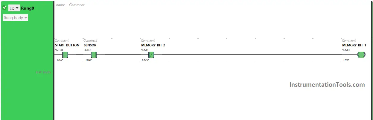
In a false state, Normally Closed Contact used for Memory Bit 2 (M1) also passes the signal to turn ON Memory Bit 1 (M0) and Memory Bit 1 (M0) turns ON.
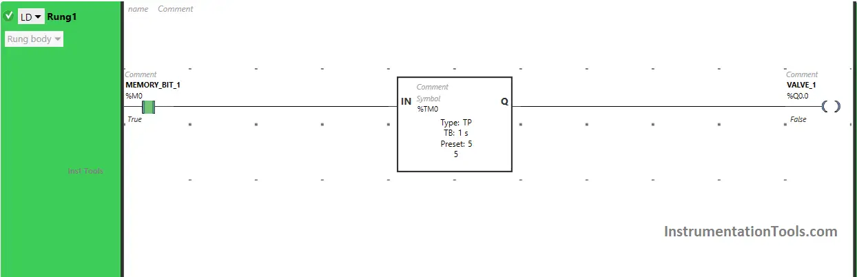
Rung 1:
When Memory Bit 1 (M0) turns ON in Rung0, Normally Open Contact used for Memory Bit 1 (M0) in Rung1 will be in True state and allow the signal to pass through it to turn ON the output Valve 1 (Q0.0) (System starts dispensing first type of food).
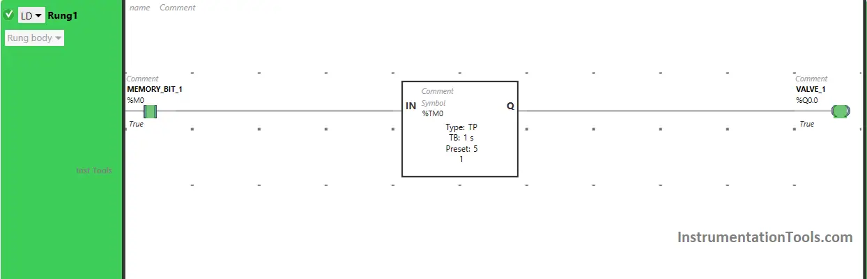
The output Valve 1 (Q0.0) will remain ON for a limited time as the Timer Function Block type TP is used to turn ON the output Valve 1 (Q0.0) for a limited time.
The time is set to 5 seconds. After 5 seconds, the output Valve 1 (Q0.0) will turn OFF (The system stops dispensing the first type of food).
Rung 2:
Also, When Memory Bit 1 (M0) turns ON in Rung0 and the output Valve 1 (Q0.0) turns OFF in Rung1 (Dispensing of First type of Food stops), the output Valve 2 (Q0.1) turns ON as Normally Open Contact used for Memory Bit 1 (M0) will be in True State and allows the signal to pass through it.
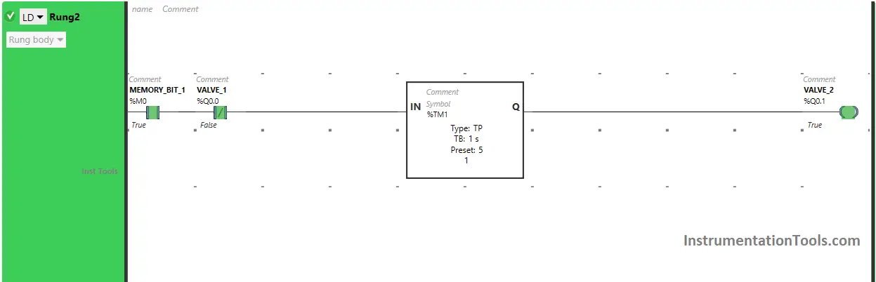
In a false state, Normally Closed Contact used for Valve 1 (Q0.0) also passes the signal to turn ON the output Valve 2 (Q0.1) (System starts dispensing the second type of food).
The output Valve 2 (Q0.1) will remain ON for a limited time as the Timer Function Block type TP is used to turn ON the output Valve 2 (Q0.1) for a limited time. The time is set to 5 seconds.
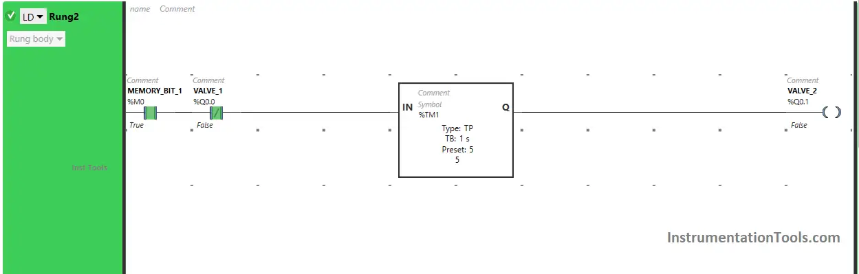
After 5 seconds, the output Valve 2 (Q0.1) will turn OFF (The system stops dispensing the second type of food).
Rung 3:
Also, When Memory Bit 1 (M0) turns ON in Rung0, the output Valve 1 (Q0.0) turns OFF in Rung1 (Dispensing of First type of Food stops) and the output Valve 2 (Q0.1) turns OFF in Rung2 (Dispensing of second type of Food stops), the output Valve 3 (Q0.2) turns ON as Normally Open Contact used for Memory Bit 1 (M0) will be in True State and allows the signal to pass through it.
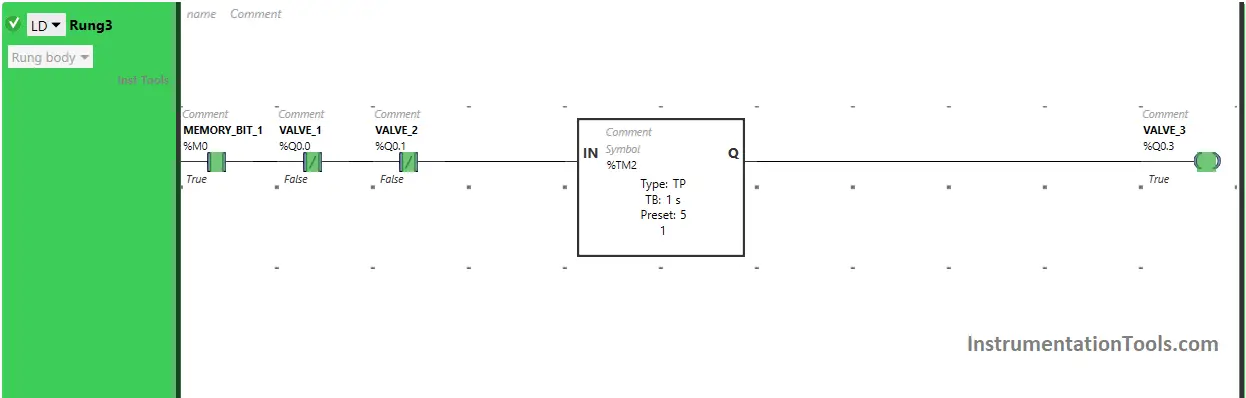
In a false state, Normally Closed Contact used for Valve 1 (Q0.0) and Valve 2 (Q0.0) also passes the signal to turn ON the output Valve 3 (Q0.2) (System starts dispensing third type of food).
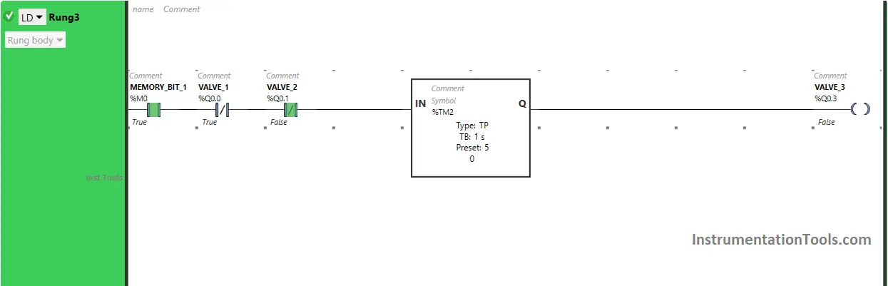
The output Valve 3 (Q0.2) will remain ON for a limited time as the Timer Function Block type TP is used to turn ON the output Valve 3 (Q0.2) for a limited time.
The time is set to 5 seconds. After 5 seconds, the output Valve 3 (Q0.2) will turn OFF (The system stops dispensing the third type of food).
Rung 4:
Also, When Memory Bit 1 (M0) turns ON in Rung0, Memory Bit 2 (M1) turns ON in Rung4 after 30 seconds as Timer Function Block type TON is used to delay the turning ON time of Memory Bit 2 (M1), and the time is set to 30 seconds.
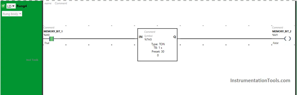
So after 30 seconds, Memory Bit 2 (M1) will turn ON but it will turn OFF within no time because in Rung0, Normally Closed Contact is used for Memory Bit 2 (M1).
In Rung0, Normally Closed Contact used for Memory Bit 2 (M1) will also turn ON and OFF within no time and the whole process will restart.
If you liked this article, please subscribe to our YouTube Channel for PLC and SCADA video tutorials.
You can also follow us on Facebook and Twitter to receive daily updates.
Read Next:
- Siemens HMI Training Tutorials and Codes
- PLC Programming with Sequencer Instruction
- PID Controllers in Closed Loop Control Systems
- Instrumentation Engineer Detail Design Phase
- How to Take Program Backup from Siemens PLC?