Inst ToolsInst ToolsInst Tools
  • Courses
  • Automation
    • PLC
    • Control System
    • Safety System
    • Communication
    • Fire & Gas System
  • Instrumentation
    • Design
    • Pressure
    • Temperature
    • Flow
    • Level
    • Vibration
    • Analyzer
    • Control Valve
    • Switch
    • Calibration
    • Erection & Commissioning
  • Interview
    • Instrumentation
    • Electrical
    • Electronics
    • Practical
  • Q&A
    • Instrumentation
    • Control System
    • Electrical
    • Electronics
    • Analog Electronics
    • Digital Electronics
    • Power Electronics
    • Microprocessor
  • Request
Search
  • Books
  • Software
  • Projects
  • Process
  • Tools
  • Basics
  • Formula
  • Power Plant
  • Root Cause Analysis
  • Electrical Basics
  • Animation
  • Standards
  • 4-20 mA Course
  • Siemens PLC Course
Reading: What is RTD Accuracy ?
Share
Font ResizerAa
Inst ToolsInst Tools
Font ResizerAa
  • Courses
  • Design
  • PLC
  • Interview
  • Control System
Search
  • Courses
  • Automation
    • PLC
    • Control System
    • Safety System
    • Communication
    • Fire & Gas System
  • Instrumentation
    • Design
    • Pressure
    • Temperature
    • Flow
    • Level
    • Vibration
    • Analyzer
    • Control Valve
    • Switch
    • Calibration
    • Erection & Commissioning
  • Interview
    • Instrumentation
    • Electrical
    • Electronics
    • Practical
  • Q&A
    • Instrumentation
    • Control System
    • Electrical
    • Electronics
    • Analog Electronics
    • Digital Electronics
    • Power Electronics
    • Microprocessor
  • Request
Follow US
All rights reserved. Reproduction in whole or in part without written permission is prohibited.
Inst Tools > Blog > Temperature Measurement > What is RTD Accuracy ?

What is RTD Accuracy ?

Last updated: December 1, 2019 12:19 pm
Editorial Staff
Temperature Measurement
1 Comment
Share
5 Min Read
SHARE

The practical accuracy of an RTD will depend on the tolerance of the RTD, the measurement temperature, the accuracy of the mating instrument, and the effects of the interconnecting lead wire and the installation.

But when we speak of the accuracy of an RTD sensor, we are usually referring to its temperature deviation or tolerance grade at some reference temperature, as its “real” tolerance is temperature dependent.

There are a number of international standards that define the tolerance and accuracy limits of RTDs. The most common standard used for grading Platinum RTDs is IEC 751 (1995).

IEC 751 defines two performance classes for 100Ω Platinum RTDs with alpha 0.00385, Class A and Class B, as follows:

RTD Accuracy

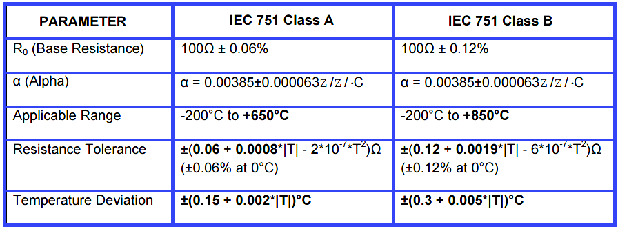
Note: The expression for Resistance Tolerance is only applicable to α=0.00385 Pt RTDs. The symbol “|T|” in the table expressions refers to the absolute value of the sensor temperature.

Other standards such as DIN 43760, BS-1904, BS EN60751 (1996), and JIS C1604 generally match the IEC 751. While IEC 751 only addresses 100Ω Platinum RTDs with alpha 0.00385, its temperature tolerance and accuracy requirements are often applied to other platinum RTD types.

For example, the JIS C1604 standard also adds recognition of the 0.003916 alpha type and applies the same tolerance standards. Performance classes A & B are also referred to as DIN A and DIN B with respect to the DIN 43760 standard. Note that Class C and Class D designations are sometimes used and each Class doubles the prior tolerance level.

DIN Standard (DIN 43760) similarly recognizes three different temperature deviation classes as follows:

DIN Class A: ±(0.15 + 0.002*|T|)  °C       (Matches IEC 751 Class A)

DIN Class B: ±(0.30 + 0.005*|T|)  °C       (Matches IEC 751 Class B)

DIN Class C: ±(1.20 + 0.005*|T|)  °C

In the US, ASTM Specification E1137 is also referenced and defines two RTD temperature tolerance grades, A and B, as follows:

Grade A: ±(0.13 + 0.0017*|T|)  °C

Grade B: ±(0.25 + 0.0042*|T|)  °C

By IEC 751, the accuracy or tolerance grade of an RTD element is a function of its resistance tolerance and its temperature deviation.

In accordance with DIN 43760 and IEC 751, its class designation will be denoted by its resistance tolerance and temperature deviation at its calibration temperature (typically 0°C) and base resistance R0 (typically 100Ω), and will be divided into two major classes as follows:

Temp & Resistance Tolerance vs Temperature for Platinum RTDs Per IEC 751 (1995) & BS EN60751 (1996)

RTD Class A & Class B Tolerance

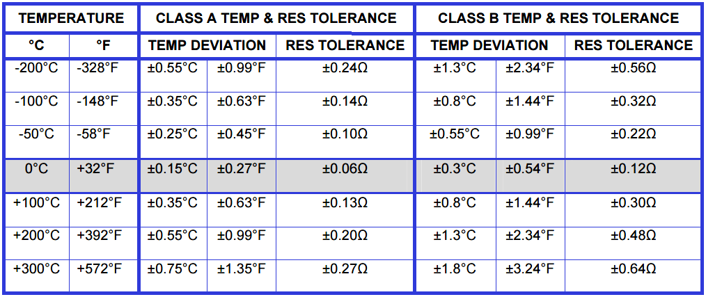
Note: The tolerances provided above are assumed to apply to three and four wire Platinum sensor connections, as two wire RTD sensor connections will require special consideration due to the negative effects of lead resistance, as two wire sensors cannot achieve these tolerances without the benefit of lead compensation provided by three and four wire sensors.

Most RTD sensors will use the Class A or Class B designation as set forth in International Standard IEC 751 and will be denoted simply by their temperature deviations at their reference temperature: Class A, with a tolerance of ±0.15°C at 0°C; or Class B, with a tolerance of ±0.3°C at 0°C. But there are additional class designations such as “1/10 DIN” and “1/3 DIN” used to denote sensors of greater precision and these will have a tolerance of 1/10 or 1/3 of the Class B specification at 0°C, respectively.

While the “accuracy” of an RTD element is usually denoted by its initial element accuracy measured at one point, usually 0°C (32°F), it does vary with temperature. Further, it is also dependent on the tolerance of the base resistance at the calibration temperature of the element.

So the effective tolerance of an RTD sensor is really a combination of both the base resistance tolerance (the resistance tolerance at the calibration temperature), and the Temperature Coefficient of Resistance tolerance (TCR or tolerance of the characteristic slope).

For most RTDs, the calibration temperature is 0°C, and it is understood that any temperature above or below this temperature will have a wider tolerance band and lower accuracy.

Also Read : How to Calculate RTD Tolerance

Article Source : Acromag

Don't Miss Our Updates
Be the first to get exclusive content straight to your email.
We promise not to spam you. You can unsubscribe at any time.
Invalid email address
You've successfully subscribed !

Continue Reading

Temperature Gauges and Elements : Detailed Specifications
Thermocouples Sources of Error
Basics of Thermocouples and RTD
Optical Pyrometer Working Principle
Non-contact Temperature Sensors
What Temperature are Celsius and Fahrenheit Value Same ?
Share This Article
Facebook Whatsapp Whatsapp LinkedIn Copy Link
Share
1 Comment
  • MD ather says:
    March 13, 2020 at 4:33 pm

    This is very interested

    Reply

Leave a Reply Cancel reply

Your email address will not be published. Required fields are marked *

Stay Connected

128.3kFollowersLike
69.1kFollowersFollow
210kSubscribersSubscribe
38kFollowersFollow

Categories

Explore More

Difference between PT100, PT1000, Nickel RTD and Balco RTD
Difficulties with Thermocouples for Temperature Measurement
Temperature Switch Working Principle
Difference Between RTD, Thermocouple and Thermistor
RTD Calculator : Calculate Resistance from Temperature
18 Temperature Sensors Fault Leads to Plant Shutdown
Temperature Calibration Bath Principle
What are the Thermocouple Applications?

Keep Learning

Temperature Measurement Questions

Interview Questions on Temperature Measurement

Temperature Switch Working

Basics of Temperature Switch

Temperature Sensors Interview Questions

Temperature Sensors Interview Questions

Temperature Scanner

Applications of Temperature Scanner

Thermocouple Calibration

Thermocouple Calibration

RTD Calculator Software

RTD Calculator Software

What to Choose RTD or Thermocouple ?

Thermocouple Temperature Range

Thermocouple Properties, Temperature Ranges, Element Construction

Learn More

Serial Communication Interview Questions

Serial Communication Interview Questions and Answers

pH Analyzers Questions and Answers

Hydrogen and Glass Electrodes Questions & Answers

capacitance probe

Capacitance Level Measurement Working Principle

How to Program Sequential Outputs in PLC

Timer-Based Sequential PLC Program with One Button

Generator Action in a Motor

What is Synchroscope ?

Phase Watcher Multiphase Flow Meter (MPFM) Procedure

PLC Sequence Programming Ladder Logic

PLC Sequence Programming Ladder Logic

Oscillating Piston Flow Meters Principle Animation

Nutating Disc Flow Meters Working Principle

Menu

  • About
  • Privacy Policy
  • Copyright

Quick Links

  • Learn PLC
  • Helping Hand
  • Part Time Job

YouTube Subscribe

Follow US
All rights reserved. Reproduction in whole or in part without written permission is prohibited.
Welcome Back!

Sign in to your account

Username or Email Address
Password

Lost your password?