Digital control valve works on the principle of a “balanced piston”. Here we will refer to the Digital control valve as “DCV” throughout this article.
The digital control valve (DCV) is being used mainly to control batches of clean liquid or gases that are in liquid forms i.e. LPG, LNG, etc, It is being configured with a metering skid for precise batching.
Please refer to Fig. 1 to understand the typical setup of batching, this can be varied as per requirement and site condition or operational needs.
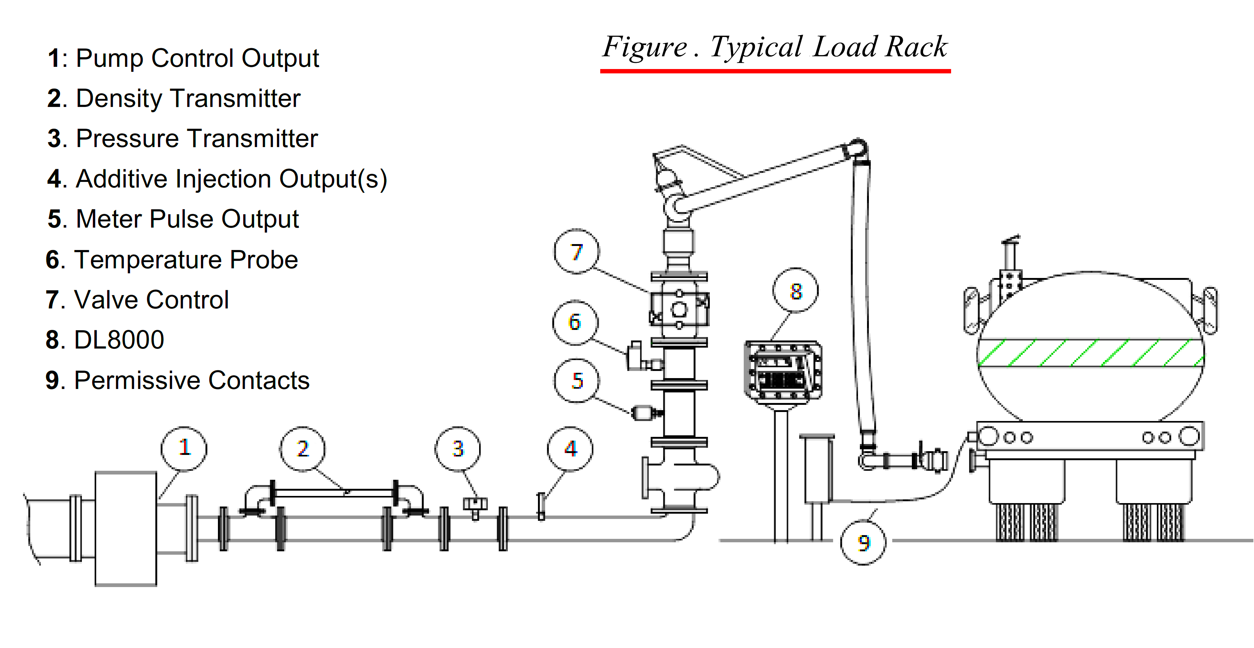
Fig.(1)- Loading batch setup.
During the automatic batch process, the digital control valve (DCV) maintains a constant flow with varying inline pressure, So it provides maximum accuracy of the flow meter which is being connected upstream of the DCV.
Understand the Automatic Batch Process
To know about DCV and its role in batching we need to understand the functionality of batching first.
Minimum setup of batch control system (Metering skid): In the inlet, there is one air eliminator provided with a strainer basket to collect foreign material and eliminate the air in the atmosphere, this air eliminator provides protection to flow meter with passing clean fluid only if membrane of strainer basket damaged it should be replaced with new one without second thought, near air eliminator a pressure transmitter will be there to measure line pressure.
After the air eliminator mass flow meter comes into the picture to measure real-time flow and density, this mass flow meter will provide pulse output to the electronic batch controller to measure the total loaded quantity.
Then digital control valve (DCV) will come into the picture with pilot control using NO NC solenoid valve tubing setup, it is spring-biased to a closed condition, pressure differential overcomes the force of the spring, causing the main valve to open and establish flow, the pilot control to vary the pressure on the spring side of the piston for position.
After DCV there will be an isolation valve, as per operational requirement, when these all things inline and normal product will go to tanker through loading arm.
To control all this process in an auto Electronic batch controller is being used, with provided interlock with the smart ground detector, from this batch controller, we can set a preset quantity to be loaded, we can give automatic pump output, it can be used to add additives in the product and mainly it controls digital control valve to maintain the flow for that it received input for flow from the mass flow meter and accordingly send command to DCV’s SOVs to maintain flow.
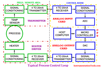
In this batch controller unit, a 4-channel meter pulse board to read pulse output from the flow meter, an analog AIO card to read 4-20 mA signal from the pressure transmitter, a DIO card to read and command to digital control valves or digital switch on loading arm, and power card to provide power supply to all these equipment.
So, this was about the batching system, let’s come to the topic and dive deep into the digital control valve.
What are Digital Control Valves?
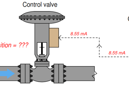
The digital control valve is a solenoid-operated device designed to provide precise flow rate control and batch delivery of liquid products, it is used in conjunction with an electronic batch control device.
The digital control valve (DCV) is automatically controlled, for low flow, shut down, and final shut off.
Principle of Operation
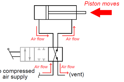
The operation of the Digital Control Valve is based on a balanced piston Principle. When pressure on both sides of the main valve piston is equal, a spring (located on the top of the piston) acts as a differential force and closes the main valve piston.
As pressure against the bottom of the piston increases and exceeds the pressure exerted against the top of the piston plus the force of the spring, the spring tension is overcome, and the valve opens.
Solenoid pilots are digitally controlled (fully open or fully closed) and are used to determine the main valve piston position required for flow control.
Control Setup
- First verify that the digital valve function is programmed properly in the batch controller, if it is not programmed properly for digital control then it will result in a poor flow rate and quality of the product.
- To achieve the maximum reliable performance of the system, control parameters such as high & low flow error, valve response time, flow rates and stop quantities are functions of system hydraulics that should be set as per customer requirements.
- The starting point for both normally open (closing speed) and normally closed (opening speed) needle valve settings are 2 turns open from fully closed.
- To finalize the setting of needle valve settings, initiate small batch delivery, Observe the low flow start, High flow rate, and low flow stop., and adjust the needle valve to set the SOV (solenoid) actuation, Typically, the solenoids should be accurate 3 or 4 times, in order the flow rate to stabilize during flow transitions-start to low flow, low flow to high flow and high flow to low stop, excessive actuations can affect the lifespan of valve components.
- The opening speed is controlled by the needle valve on the downstream side of the valve (normally closed solenoid), To increase the opening speed, turn the needle valve counterclockwise, To decrease the opening speed, turn the needle valve clockwise.
- The closing speed is controlled by the needle valve on the upstream side of the valve (normally open solenoid), To increase the closing speed, turn the needle valve counterclockwise, To decrease the closing speed, turn the needle valve clockwise.
- The flow profile error limits also affect the number of solenoid actuations, the error limits should be set to the maximum limits required to keep the flow rate in control. The minimum error limit is a function of meter pulse frequency; the larger the K-factor the better. A general frequency value is a minimum of 50Hz at the low flow rate.
Typical Installation and Various Positions of Digital Control Valve (DCV)
Closed or Closing position: First check the fig.2 and understand before we see it in detail.
Here we had taken the reference of digital control valve – Make: Brodie, Model: BV88
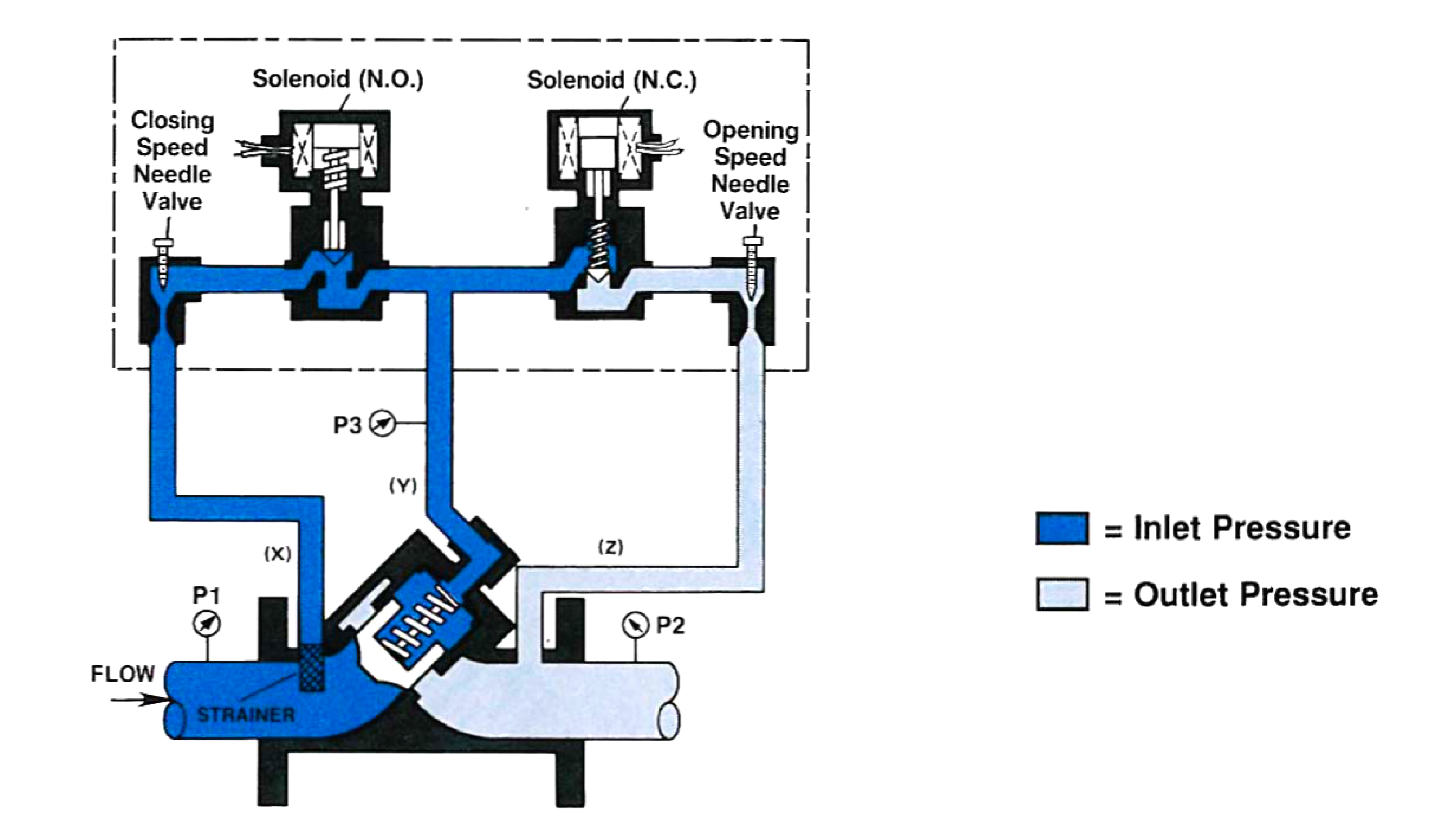
Fig. (2)
The normally closed solenoid is closed, the normally solenoid is open, the Y-port (P3) to Z-port (P2) is closed, X-Port (P1) and Y-Port (P3) pressures are balanced, the main valve spring being the deferential force, closes the piston and keeps it seated.
Opened or Opening condition: First check fig.3 and understand before we see it in detail.
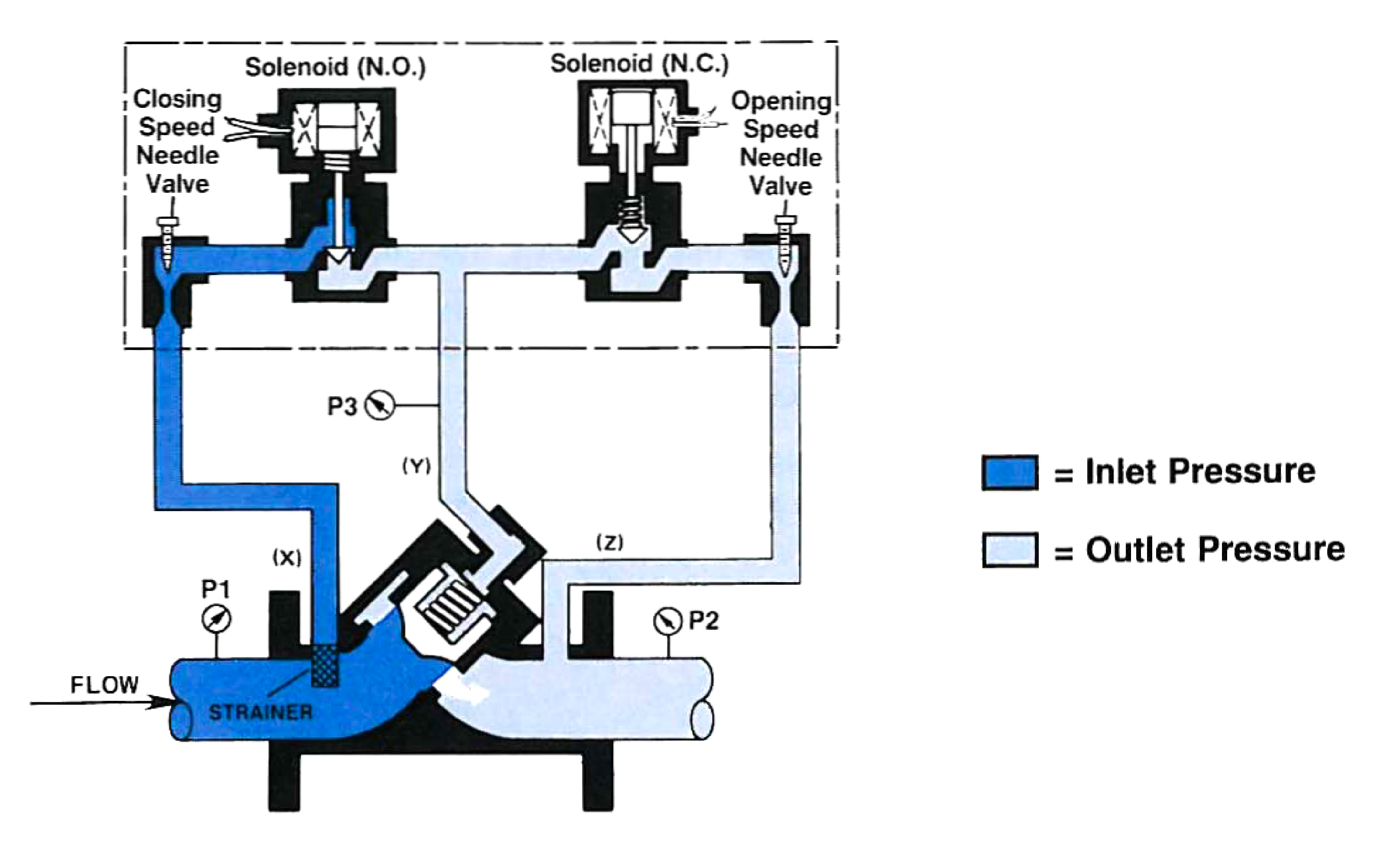
Fig. (3)
The normally closed solenoid is open. The normally open solenoid is closed. Y-Port (P3) is open to Z-Port (P2).
X-Port (P1) is closed off by the normally open solenoid. The pressure on the bottom of the piston (P1) is greater than the pressure at (P3) plus the spring force; (P1 – P2) is equal to or greater than the spring force. Therefore, (P1) pressure pushes the spring open.
Controlling position: In Fig.4 we can see the position of the valve during controlling it.
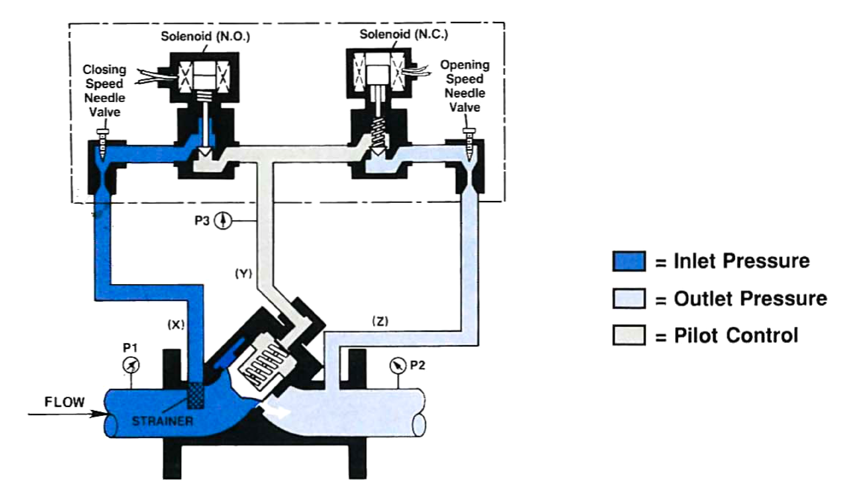
Fig. (4)
The normally closed solenoid is closed. The normally open solenoid is closed. Y-Port (P3) to Z-Port (P2) is closed.
X-Port (P1) to Y-Port (P3) is closed. Note: The product cannot flow to or from the top of the piston (Y-Port).
The piston is hydraulically locked in position until the PC-IMS commands the valve to open or close as required to maintain the desired flow rate.
Design Features of Digital Control Valve
- It has modular construction as all internal parts including the seat ring can be removed with cylinder assembly without disturbing line connections.
- No diaphragm or stuffing boxes.
- 45 Degree body design assures high capacity.
- Positive shut-off (within 2-3 seconds).
- Uniform speed of response (2-3 seconds maximum).
- Linear control characteristics.
- Inherently checks reverse flow.
- O-ring seat.
- Tapered ports for a better low-flow response.
- Fail-safe close on failure of power.
- Precise flow rate and batch control.
Material of Construction
- Main valve body: Steel, ASTM-A216-GR-WCB
- Main valve cylinder: 2” through 6” 17-4 PH stainless steel.
- Main valve piston: Stainless steel.
- Seat ring: Stainless Steel.
- Seals: Viton-A.
Applications of Digital Control Valves
Batch control of clean liquids and gases with flow-limiting capabilities when used with electronic presets capable of digital control.
Typical Look
You can see the typical look of DCV in Fig. (5)
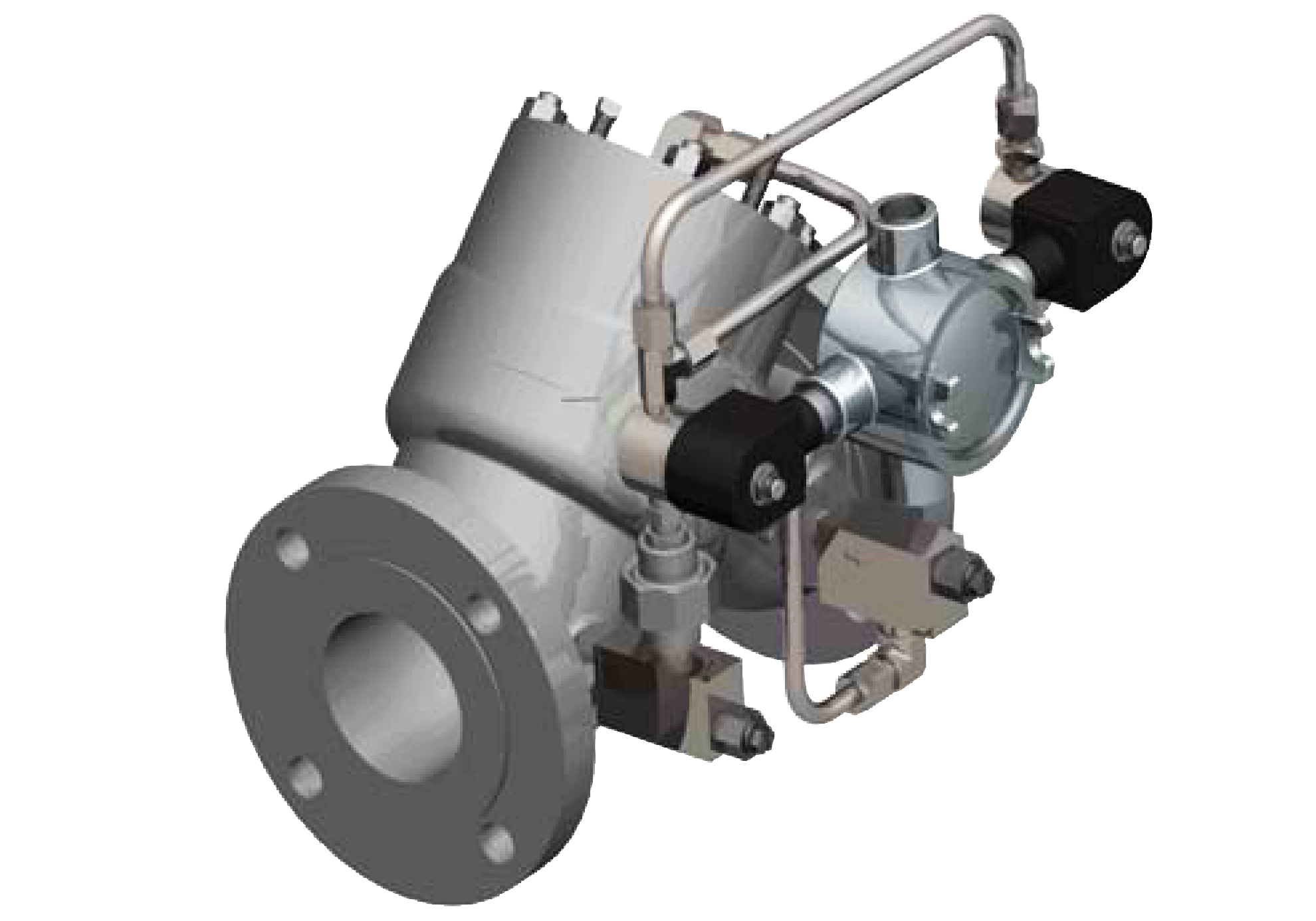
Fig.(5)
If you liked this article, then please subscribe to our YouTube Channel for Instrumentation, Electrical, PLC, and SCADA video tutorials.
You can also follow us on Facebook and Twitter to receive daily updates.
Read Next:
- Quick Exhaust Valves
- On-Off Valve Problems
- Control Valve Design Factors
- Solenoid and Motorized Valves
- Gate Valves and Globe Valves