Inst ToolsInst ToolsInst Tools
  • Courses
  • Automation
    • PLC
    • Control System
    • Safety System
    • Communication
    • Fire & Gas System
  • Instrumentation
    • Design
    • Pressure
    • Temperature
    • Flow
    • Level
    • Vibration
    • Analyzer
    • Control Valve
    • Switch
    • Calibration
    • Erection & Commissioning
  • Interview
    • Instrumentation
    • Electrical
    • Electronics
    • Practical
  • Q&A
    • Instrumentation
    • Control System
    • Electrical
    • Electronics
    • Analog Electronics
    • Digital Electronics
    • Power Electronics
    • Microprocessor
  • Request
Search
  • Books
  • Software
  • Projects
  • Process
  • Tools
  • Basics
  • Formula
  • Power Plant
  • Root Cause Analysis
  • Electrical Basics
  • Animation
  • Standards
  • 4-20 mA Course
  • Siemens PLC Course
Reading: Parallel Circuit
Share
Notification Show More
Font ResizerAa
Inst ToolsInst Tools
Font ResizerAa
  • Courses
  • Design
  • PLC
  • Interview
  • Control System
Search
  • Courses
  • Automation
    • PLC
    • Control System
    • Safety System
    • Communication
    • Fire & Gas System
  • Instrumentation
    • Design
    • Pressure
    • Temperature
    • Flow
    • Level
    • Vibration
    • Analyzer
    • Control Valve
    • Switch
    • Calibration
    • Erection & Commissioning
  • Interview
    • Instrumentation
    • Electrical
    • Electronics
    • Practical
  • Q&A
    • Instrumentation
    • Control System
    • Electrical
    • Electronics
    • Analog Electronics
    • Digital Electronics
    • Power Electronics
    • Microprocessor
  • Request
Follow US
All rights reserved. Reproduction in whole or in part without written permission is prohibited.
Inst Tools > Blog > Electrical Theory > Parallel Circuit

Parallel Circuit

Last updated: July 23, 2018 11:06 am
Editorial Staff
Electrical Theory
No Comments
Share
1 Min Read
SHARE

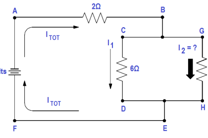
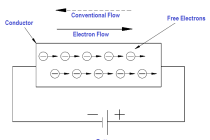
Parallel circuits are those circuits which have two or more components connected across the same voltage source (Figure 17). Resistors R 1 ,R2, and R3 are in parallel with each other and the source.

Each parallel path is a branch with its own individual current. When the current leaves the source V, part I1 of IT will flow through R1; part I2 will flow through R2 ; and part I3 will flow through R3 . Current through each branch can be different; however, voltage throughout the circuit will be equal.

V = V1 = V2 = V3

Parallel Circuit

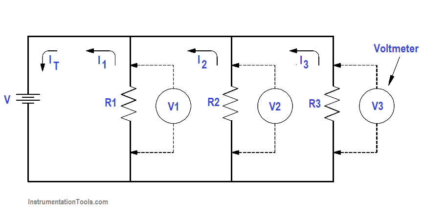
Figure 17 Parallel Circuit

Equivalent Resistance

In a parallel circuit, the total resistance of the resistors in parallel is referred to as equivalent resistance. This can be described as the total circuit resistance as seen by the voltage source. In all cases, the equivalent resistance will be less than any of the individual parallel circuit resistors.

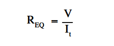
Using Ohm’s Law, equivalent resistance (REQ ) can be found by dividing the source voltage (V) by the total circuit current (IT ), as shown in Figure 17.

Parallel Circuit Equivalent Resistance Formula

Don't Miss Our Updates
Be the first to get exclusive content straight to your email.
We promise not to spam you. You can unsubscribe at any time.
Invalid email address
You've successfully subscribed !

Continue Reading

Transformer Voltage Ratio
Transformer Losses and Efficiency
Power Factor Meter Principle
Discharge and Charging of Lead-Acid Battery
Impedance in RC Circuits
Parallel Short Circuit Faults
Share This Article
Facebook Whatsapp Whatsapp LinkedIn Copy Link
Share
Leave a Comment

Leave a Reply Cancel reply

Your email address will not be published. Required fields are marked *

Stay Connected

128.3kFollowersLike
69.1kFollowersFollow
210kSubscribersSubscribe
38kFollowersFollow

Categories

Explore More

Capacitance and Capacitive Reactance
Moving Iron Vane Meter Movement
Transformer Mutual Induction
Ohm Meter
Inductive Time Constant
Block Diagram
AC Motor Theory
Battery Terminology

Keep Learning

Voltage Divider

Voltage Divider

Parallel Circuit Parallel Current Calculations

Parallel Circuit Current Calculations

Left-hand Rule for Current Carrying Conductors

Magnetism

Armature Current in a DC Motor

DC Motor Torque

Calculate Power in Series RL Circuit

Calculate Power in Series RL Circuit

Transformer Operation Under No-Load

Transformer Operation Under No-Load

Properties of Conducting Materials

Resistivity

Calculate Power in Series RCL Circuit

Calculate Power in Series RCL Circuit

Learn More

PLC Programming for Pumping and Draining System

PLC Programming for Pumping and Draining System

SCADA backup too has been configured

FactoryTalk Studio and SQL Server for Data Logging

Timer-based vacuum cleaner in Schneider PLC

Schneider Electric PLC Timer Problem: Vacuum Cleaner

Left-Hand Rule for Generators

DC Generator Theory

How to Get a PLC Programming Job With No Experience

How to Get a PLC Programming Job With NO Experience?

SCR Switching Characteristics

SCR Switching Characteristics

Backwashing Precoat Filters

Backwashing Precoat Filters

Classification of Bridge Circuits

Classification of Bridge Circuits

Menu

  • About
  • Privacy Policy
  • Copyright

Quick Links

  • Learn PLC
  • Helping Hand
  • Part Time Job

YouTube Subscribe

Follow US
All rights reserved. Reproduction in whole or in part without written permission is prohibited.
Welcome Back!

Sign in to your account

Username or Email Address
Password

Lost your password?