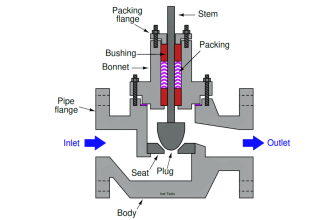
In the PLC timer application for security camera recording, when motion is detected then camera starts recording and lights also turn on.
Note: This is a basic PLC program prepared for beginners to learn the ladder logic. The real-world application will be equipped with more safety logic and control devices. This is just for learning purposes.
PLC Timer Application
Problem Statement:
Design a PLC ladder logic for the following application.
We are using one sensor to control the Camera and Light.
When motion is detected, a camera should start recording and continue for 25 seconds. With that, lights should also be turned at an interval of 2 seconds.
PLC Training Videos Series
The PLC training video series is prepared with concepts ranging from basic to advanced with a simple explanation.
PLC Inputs
The inputs of the program are listed here.
Sensor: I0.0
PLC Outputs
The outputs of the program are listed here.
Camera: Q0.0
Light: Q0.1
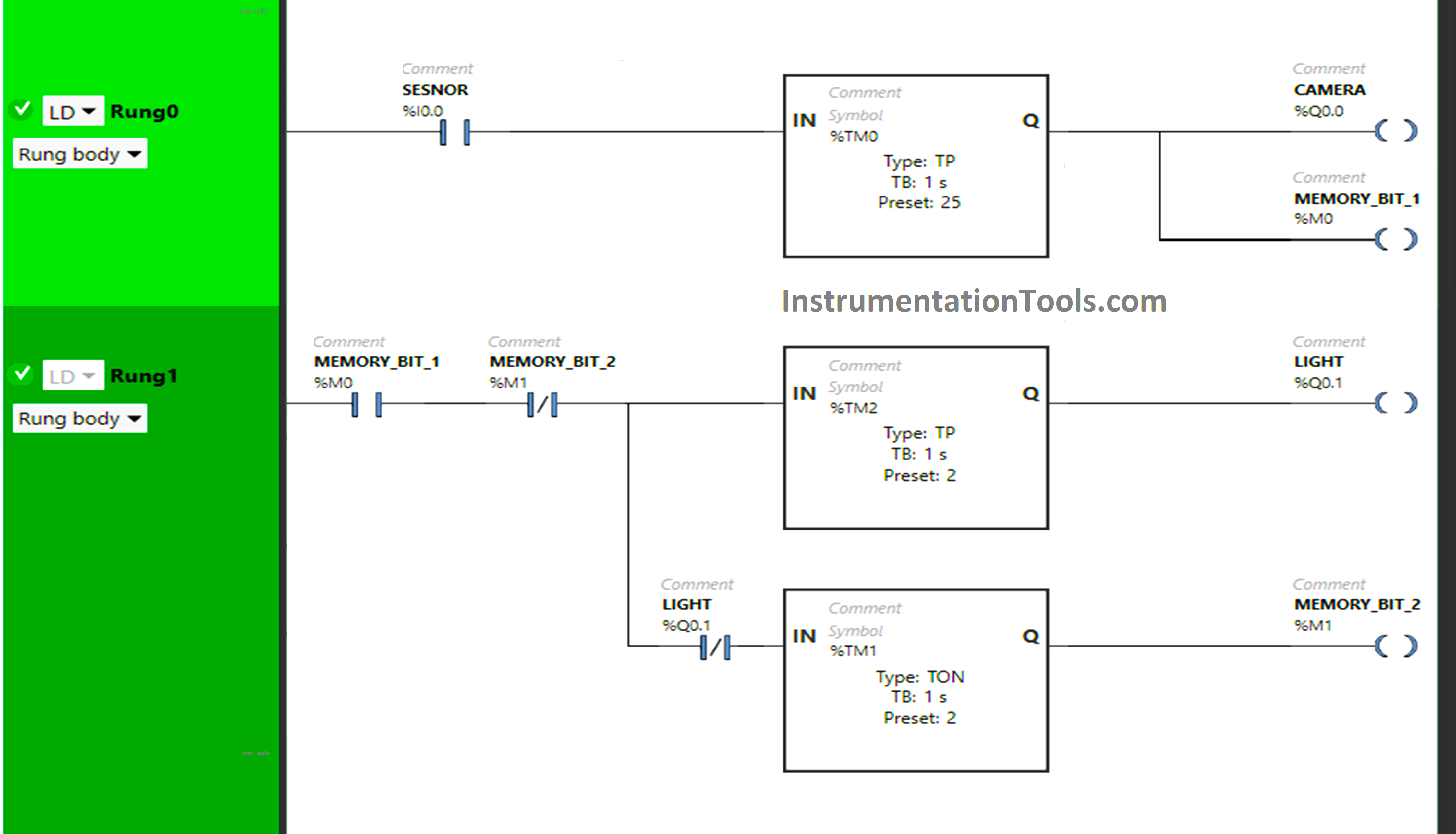
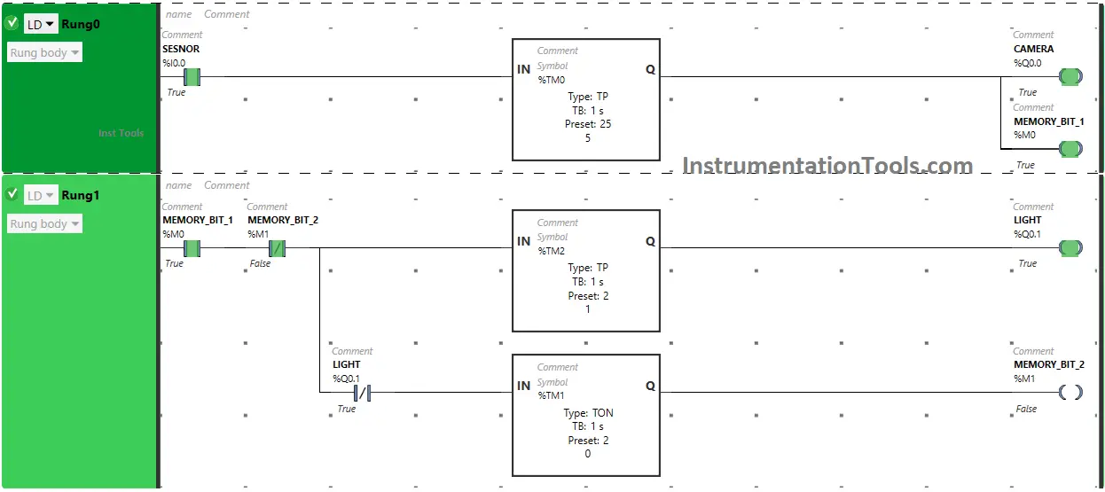
Security Camera Ladder Logic
Program Explained
We have used Normally Open Contact for Sensor (I0.0) and Memory Bit 1 (M0).
In Rung0:
1) Normally Open Contact is used for Sensor (I0.0) to Turn ON the output Camera (Q0.0) and Memory Bit 1 (M0).
2) Timer Function Block type TP is used to Turn ON the output Camera (Q0.0) and Memory Bit 1 (M0) for a limited time.
In Rung1:
1) Normally Open Contact is used for Memory Bit 1 (M0) to Turn ON the output Light (Q0.1) and Memory Bit 2 (M1).
2) Normally Closed Contact is used for Memory Bit 2 (M1) to turn OFF the output Light (Q0.1) and Memory Bit 2 (M1).
3) Normally Closed Contact is used for Light (Q0.1) to turn ON Memory Bit 2 (M1).
4) Timer Function Block type TP is used to Turn ON the output Light (Q0.1) for a limited time.
5) Timer Function Block type TON is used to delay the turning ON time of Memory Bit 2 (M1) for some time.
Result: When motion is detected
When Senor (I0.0) gets activated (Sensor detects motion), the output Camera (Q0.0) turns ON (Camera starts recording) and Memory Bit 1 (M0) also turns ON in Rung0 as Normally Open Contact used for Sensor (I0.0) will be in true state and allows the signal to pass through it.
The output Camera (Q0.0) and Memory Bit 1 (M0) turn ON but only for a limited time as Timer Function Block type TP is used to Turn ON the output Camera (Q0.0) and Memory Bit 1 (M0) for a limited time. The time is set to 45 seconds.
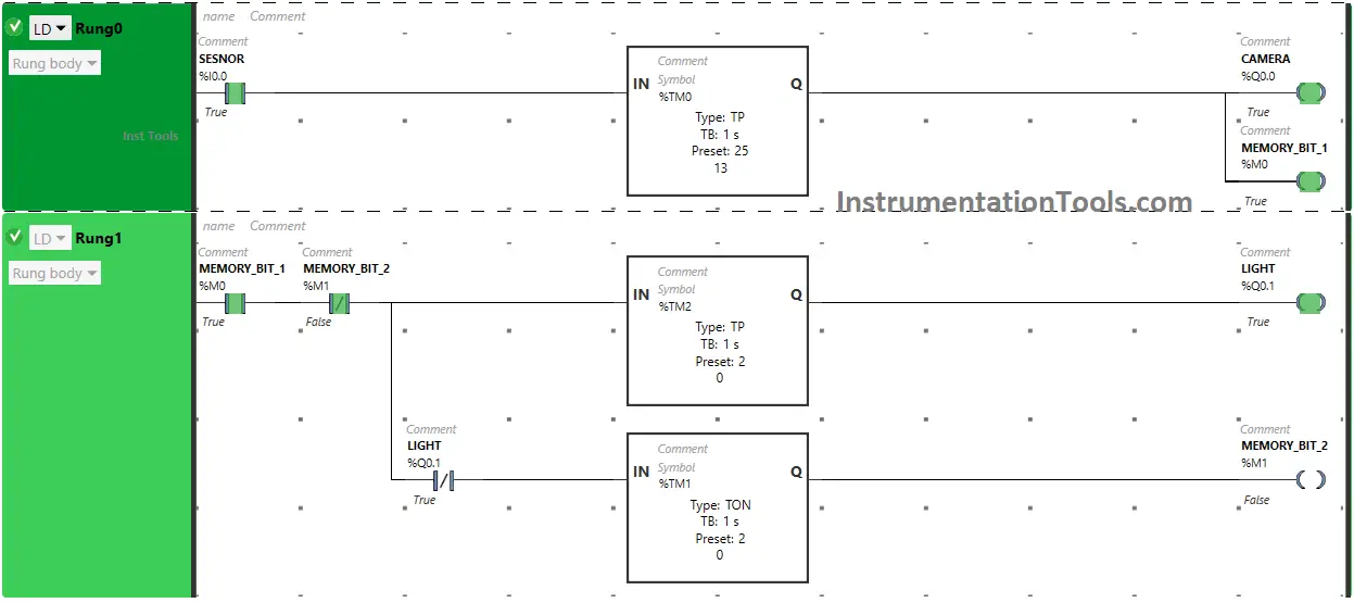
After 45 seconds, the output Camera (Q0.0) and Memory Bit 1 (M0) will turn OFF. When Memory Bit 1 (M0) turns ON in Rung0, Normally Open Contact used for Memory Bit 1 (M0) in Rung1 will be in a True state and allow the signal to pass through it.
In a false state, Normally Closed Contact used for Memory Bit 2 (M1) also passes the signal to turn ON the output Light (Q0.1). The output Light (Q0.1) turns OFF after some time as Timer Function Block type TP is used to Turn ON the output Light (Q0.1) for a limited time. The time is set to 2 seconds.
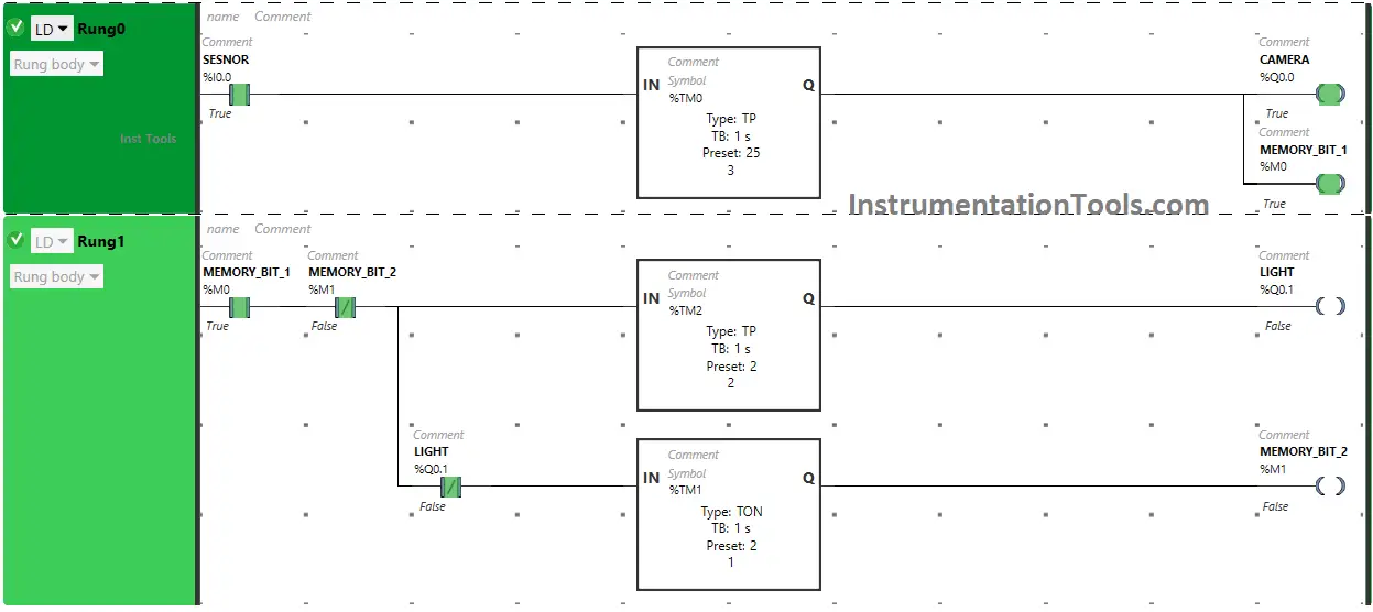
After 2 seconds, the output Light (Q0.1) will turn OFF. When the output Light (Q0.1) turns OFF, Normally Closed Contact used for Light (Q0.1) will be in a false state and pass the signal to turn ON Memory Bit 2 (M1) and Memory Bit 2 (M1) turns ON but after a delay of 2 seconds as Timer Function Block type TON is used to delay the turning ON time of Memory Bit 2 (M1). The time is set to 2 seconds.
After 2 seconds, Memory Bit 2 (M1) will turn ON but it will turn OFF within no time because in Rung1, Normally Closed Contact is used for Memory Bit 2 (M1). In Rung1, Normally Closed Contact used for Memory Bit 2 (M1) will also turn ON and OFF within no time and the whole process will restart in Rung1.
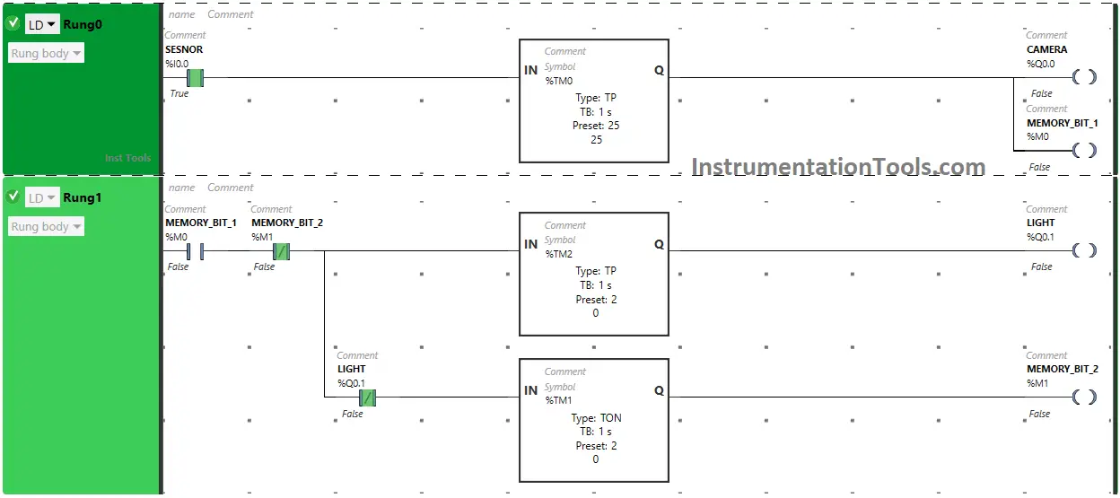
In Rung0, when Timer Function Block Type TP reaches its time limit i.e. 25 seconds, the output Camera (Q0.0) will turn OFF ( Camera stops recording) and Memory Bit 1 (M0) will also turn OFF.
As Memory Bit 1 (M0) turns OFF in Rung0, Normally Open Contact used for Memory Bit 1 (M0) in Rung1 will be in a false state and does not allow the signal to pass through it and the whole process stops in Rung1.
If you liked this article, please subscribe to our YouTube Channel for PLC and SCADA video tutorials.
You can also follow us on Facebook and Twitter to receive daily updates.
Read Next:
- Single-acting Cylinder PLC Logic Operation
- Free Omron PLC Online Training Course Online
- User-Defined Data Types and Function Blocks
- Machine Expert Basic versus Machine Expert
- How to Configure Distributed IO in a PLC Project?