The Continuity Equation and the Bernoulli Equation are the basis for all types of differential pressure flow measurement.
(Explanation of these equations is not included in this article).
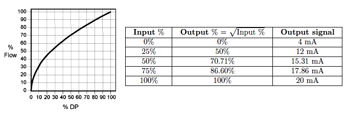
Square Root Relationship
Since, Q ∝ √ΔP.
Where, Q = Flow rate & ΔP = Differential pressure across the plate.
Turndown of differential pressure smart transmitters available in the market can go up to 200:1. So, flow rangeability (ratio of maximum to minimum flow) can be 14:1.
(Note: Rangeability of a sensor defines the measurement range over which the error statement, in the units of a percentage of actual reading is guaranteed.)
However, the standard differential pressure transmitters available in the market with high repeatability and advanced features can generally go up to the turndown of 100:1. So, flow rangeability can be achievable up to 10:1.
When flow rangeability required above 10:1, the use of two orifice plates of different capacities, two differential-pressure flow transmitters with different ranges, or both is generally recommended.
Limitations arise in the accurate measurement of the corresponding extremely wide range of differential pressure; for example, a 20:1 flow variation results in a 400:1 variation in differential pressure.
PS: It is also desirable to have the manufacturers always state not only the inaccuracy of their products but also the rangeability/turndown over which that inaccuracy statement is valid.
In principle, 10:1 to 14:1 flow rangeability and 100:1 to 200:1 DP turndown is the maximum limit while selecting a single Orifice plate as a Flow element.
Density
Fluid density is involved in the determination of either mass flow rate or volume flow rate. In other words, diff. pressure-type flow meters do not read out directly in either mass or volume flow.
Q = K ( √∆P / ρ )
Where Q = Flow rate, K = Constant, ρ = Mass density of fluid, ∆P = P1 – P2
Another important relation is,
Mass flow rate= Density x Volume flow rate
The fact that density appears as a square root gives differential pressure type flow metering an actual advantage, particularly in applications where measurement of mass flow is required.
Due to this square root relationship, any error that may exist in the value of the density used to compute mass flow is substantially reduced; a 1% error in the value of the fluid density results in a 0.5% error in calculated mass flow.
This is particularly highly important in gas flow measurement, where the density may vary over a considerable range and where operating density is not easily determined with high accuracy.
Pressure & Temperature compensation shall be implemented in the control system when higher accuracy is required in the gas flow measurement. Nowadays, also multivariable transmitters are available in the market.
Beta (β) Ratio
The beta ratio is the ratio between the diameter of the restriction and the inside diameter of the pipe.
β (Beta) = Orifice Bore Diameter (d) / Pipe Internal Diameter (D)
There is no specific range of Beta ratio has been standardized. However, it is recommended to be in the range of 0.2 to 0.7 Due to the following reasons.
β ratio < 0.2 Means:
- Orifice bore diameter is relatively smaller.
- Higher flow restriction.
- Higher pressure drop.
- More probability that Permanent Pressure Loss(PPL) exceeds expected PPL considered in Process Hydraulics.
- Higher chances of Cavitation & Flashing, since higher pressure drops, allow the process to go further down below the Vapor pressure.
- Increases Uncertainty/ Decreases accuracy.
β ratio > 0.7 Means:
- Orifice bore diameter is relatively bigger.
- Lower flow restriction.
- Lower pressure drop.
- Difficult to measure lower pressure.
- Increases Uncertainty/ Decreases accuracy.
However, some Tools/Softwares calculate from 0.15 to 0.75 as long as all process parameters, Differential Pressure Range, Permanent Pressure Loss (PPL), Flow Rangeability, and Accuracy, etc. fit together and do not give any error messages for the user.
The study, experiments, and proven installations suggest that the best accuracy of the Orifice plate is achievable when the β ratio is between 0.2 – 0.7.
Reynolds Number
Reynolds number expresses the ratio of inertial forces to viscous forces.
Re = VDρ / µ
Where, Re = Reynolds number; V = Velocity; D = Pipe Diameter; ρ = Density; µ = Absolute Viscosity
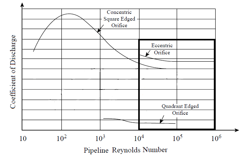
At low Reynolds numbers, the Flow profile gets disturbed, and the flow coefficient increases. So, Reynolds’s numbers more than 10,000 are recommended. Since discharge co-efficient is constant as shown in the graph below.
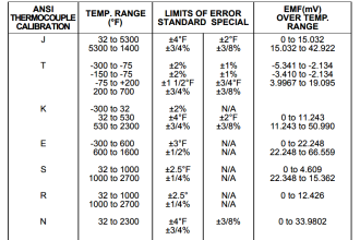
Selection of Differential Pressure Transmitter Range
The most common differential-pressure range for orifices is 0 to 100 in. of water (0 to 2500 mmH2O or 0 to 25 kPa) for full-scale flow.
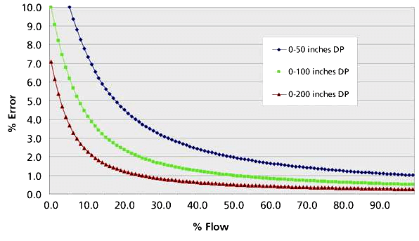
This range is high enough to minimize errors due to a change in density of liquid due to change in Temperature.
Most differential-pressure-responsive devices develop their maximum accuracy in or near this range. See the below graph Flow vs. Error.
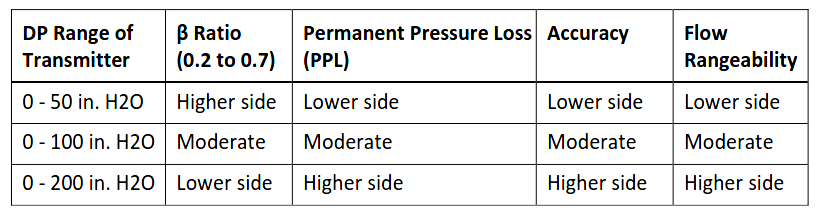
Based on the requirement of Permanent Pressure Loss (PPL), Flow rangeability/turndown, and accuracy from Process, suitable differential pressure range from the above table can be selected.
Location of Pressure Taps
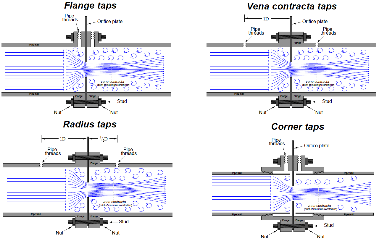
Flange Taps
- Preferred from Line size 2” and larger.
- The manufacturer of the orifice flange set drills the taps so that the centrelines are 1 in. (25 mm) from the orifice plate surface.
- Flange taps are not recommended below 2 in. (50 mm) pipe size and cannot be used below 1.5 in. (37.5 mm) pipe size, since the vena contracta may be closer than 1 in. (25 mm) from the orifice plate.
Venacontractra & Radius Taps
- Taps at 1D upstream and a downstream tap located at the point of minimum pressure.
- Vena contracta taps offer the greatest differential pressure for any given flow rate, but require precise calculations to properly locate the downstream tap position.
- Radius taps are an approximation of vena contracta taps for large pipe sizes (one-half pipe diameter downstream for the low-pressure tap location).
- An unfortunate characteristic of both these taps is the requirement of drilling through the pipe wall.
- Not only does this weaken the pipe, but the practical necessity of drilling the tap holes in the installed location rather than in a controlled manufacturing environment means there is considerable room for installation error.
Corner Taps
Corner taps must be used on small pipe diameters where the vena contracta is so close to the downstream face of the orifice plate that a downstream flange tap would sense pressure in the highly turbulent region (too far downstream).
Installation
To avoid errors resulting from disturbance of the flow pattern due to valves, fittings, and so forth, a straight run of the smooth pipe before and after the orifice is recommended.
The required length depends on the β ratio and the severity of the flow disturbance based on upstream piping components which cause flow profile disturbances.
The upstream straight run can be from 40 D to 20D and the downstream side shall be 5D.
Where it is not practical to install the orifice in a straight run of the desired length, the use of a straightening vane to eliminate swirls or vortices is recommended.
Interest to add any further points? Share with us through below comments section.
Author: Tapan Bhavsar
Read Next:
- Flowmeter Control Strategy
- What is Averaging Pitot Tube?
- Basics of Venturi Flow Meter
- Differential Pressure Flowmeter
- Flow Transmitter Square-Root


How about the use of composite flange if the pipe straight lenght cannot be achieved.
Length and run of process tubing to the transmitter is also critical, particularly when fiscal measurements are required.