Instrumentation engineering root cause analysis of seal pressure instruments, gauges, transmitter, switches, and DP transmitters.
| Article Type: | Root Cause Analysis (RCA) |
| Category: | Instrumentation |
| Equipment Type: | Sensors |
| Author: | S. Raghava Chari |
Note: This root cause analysis (RCA) is from real-time scenarios that happened in industries during the tenure of two or three decades ago. These articles will help you to improve your troubleshooting skills and knowledge.
The abbreviation SPI covers Seal Pressure Gauges (PG), Pressure Transmitter (PT) and Pressure Switches (PS) and SDPT for Seal Differential Pressure Flow and Level Transmitters.
Why use Seal Pressure Instruments (SPI)?
Body Type Seals (BTS fig 2) common for pipeline flowing ambient temp congealing liquids pressure measuring and flanged seals (FS fig 3) fitted SPI for vessels. Few such liquids examples are coal tar, molten sulfur, urea melt etc.
Such liquids stagnating in the process leads to the instruments attain ambient temperatures and solidify. Hence the instruments don’t read. Hence, the seals.
Seal details follow:
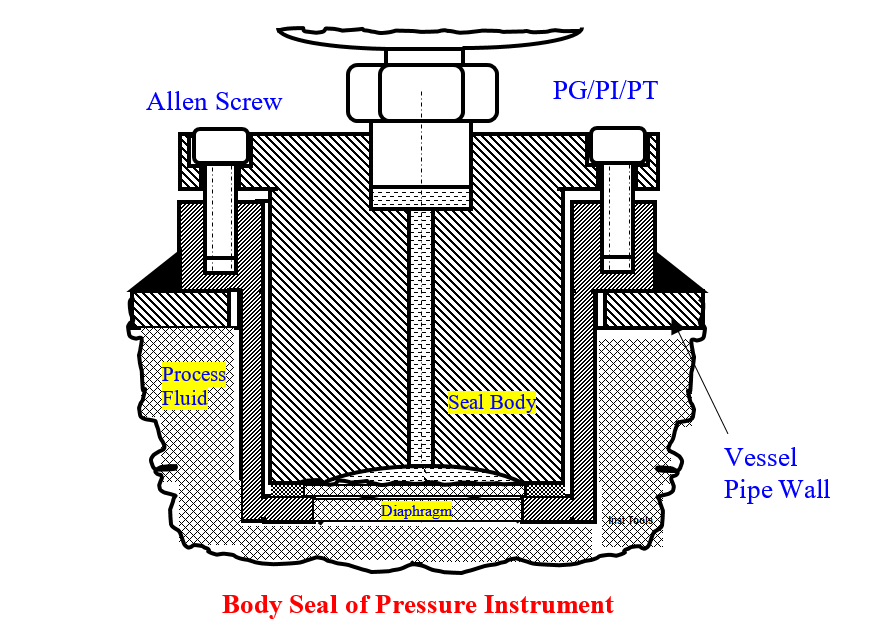
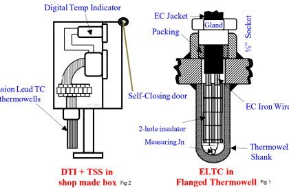
Body Type Seals
A BTS (fig 2) consists of seal body with a factory welded 0.015 mm thick diaphragm (D). A PG or other PI either directly screws on to seal body (SB) top, or capillary connects to it. BTSs of process compatible materials are available.
The factory evacuates the assembly and fills with silicone or other oils. SB bolts on welded to pipeline weldolet (W).
Suitable gasket e.g. serrated 3 mm thick SS 316 ring makes the installation leak tight.Field crew bolts the BTS to W with factory supplied special high tensile Allen screws. Commercial studs and nuts are unsuitable
Fig 2 shows that the seal body extends into the pipe bore, where hot flowing process liquid always remains liquid and hence exerts pressure on the diaphragm.
The oil fill communicates the line pressure to the top mounted PI/PG/PS for reliable and failure free readings.
On the other hand, had we installed the instrument conventionally, the liquid would stagnate in the lead to the instrument, eventually cool down to ambient temp, freeze the instrument would not read the pressure.
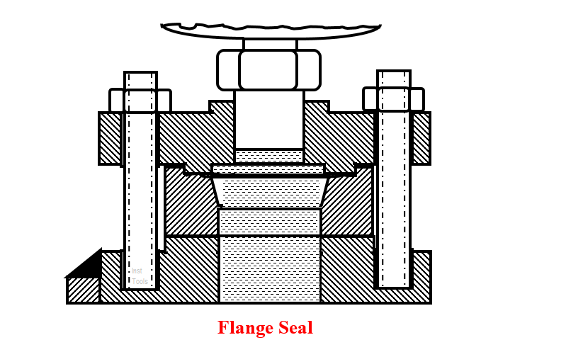
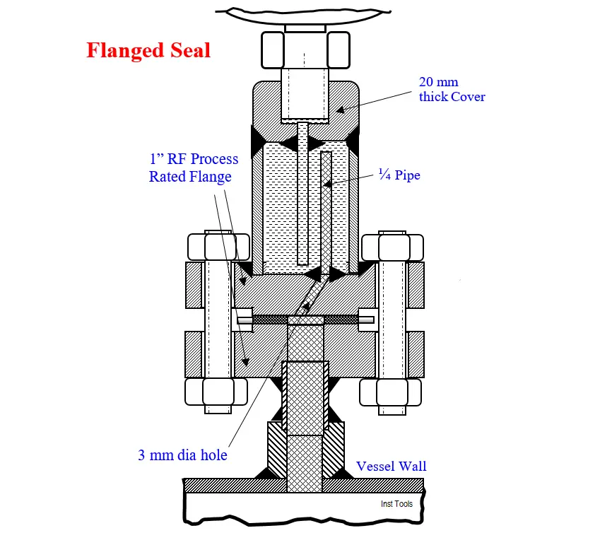
Flanged Seal (FS) (fig 3) essentially works the same way, a diaphragm welded to a 1” RF flange of process suitable rating and material replaces the SB and bolts to the pipeline short nozzle flange (fig 3)
Seal Problems
Though the seal instruments do fine in other Urea Processes, unfortunately they did not in a Total Recycle Process Urea Plant. The process engineers to whom I pointed out this did not take it seriously and apply their minds.
Faced problems are:
- Diaphragm pinholes appearing within few days use rendered the SPIs worthless
- Consequently the connected to seal pressure instruments e.g. PI, PT, or PS and associated automatic control and alarm did not work
- No field repair possibilities
- In the absence isolating block valves, crew putting new instruments involves plant shutdowns (SD). Urea plant shutdowns and re-start are very difficult, time and efforts intensive. Hence, plant operation continued till an opportune SD.
- Such blind plant runs are risky
- Too high seal instrument costs and long delivery times aggravated the above problems, besides crippling the company financially
Author’ tried Solutions
The author tried different solutions as mentioned below.
Pinholes Prevention
The SPIs with ½ mm thick PTFE barriers discs to prevent process fluid wetting the diaphragms calibrated well; however the diaphragms pinholes forming persisted as before; hence the problems too.
Diaphragm Replacement Attempts
A. Diaphragm Sandwiched Between a PTFE Gasket and Seal Body Bottom Screwed Cover (Fig 3):
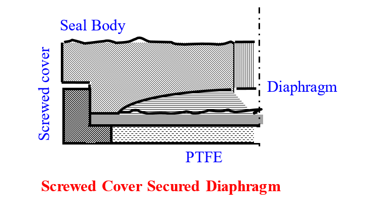
This too shop calibrated well; however, the well wrench and cheater tightened screwed cover was so loose after calibration that crew hand unscrewed the cover.
Since, no other gasket is suitable the author discarded it.
B. Weld New Diaphragm to the Body
The author guided workshop crew successfully argon arc welded the thin diaphragm to SB’s as under:
- Reduce SB length by 3-mm at the diaphragm end, and weld edge prepare
- Make a 3-mm thick ring of OD = Seal body diaphragm end, ID = OD-16 and edge prepare
- Tightly vice grip the seal body exposing 30% periphery with diaphragm sandwiched between body and ring.
- Argon arc weld the exposed periphery; complete welding the entire periphery re-gripping the assembly few times.
- 100-200 mm WC pressure air leak test and correct
- Machine the weld flush with SB
- Screw in the PG/PT directly on SB to minimize the number of joints.
Evacuation and Oil Filling the Assembly
Connect the readied seal instrument as in fig 4 using 6-mm metal / nylon tubes. Close needle Valve V‑2 and open V‑1.
Start the pump. The initial rapid bubbling in the oil would reduce to 3‑5 bubbles / mt in about 1-minute.
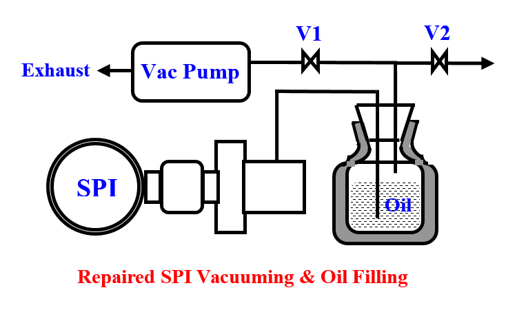
Otherwise, one or more leaky joints lets air in. Identify and correct. Hold 4-5 bubble rates for about 5 minutes. Evacuation is adequate Close V‑1 and open V-2. Atmospheric pressure oil fills the SPI completely.
Apply 50 mm air pressure via V-2 for double sure fill. Carefully disconnect FP and plug it taking care to avoid spill. Wipe and solvent clean plug area. Apply epoxy or other seal as abundant leak prevention measure.
Calibrate the assembly on a Dead Weight Tester
This method of restoring the failed instruments saved over Rs. 10 million per annum by way of no purchase of numerous of new assemblies.
However, poor diaphragm lives still plagued the plant necessitating the Author inventing No Diaphragm Seal Instruments (NDSI) – the ultimate solution!
No Diaphragm Seal Instruments (NDSI)
Below listed steps convert diaphragm seals into No Diaphragm Seals (NDS)
- Remove the failed diaphragm from the seal body (SB).
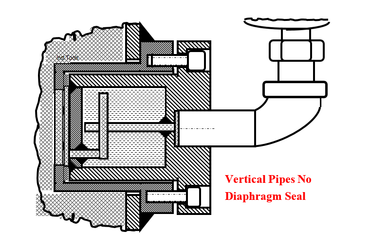
- Modify SB as in fig 5 for horizontal line pressure taps and as in fig 6 for vertical pipelines
- Fill condensate, via the instrument accepting
- ½” threaded port and screw the instrument to that port. This way gone are the fragile
- capillary connection and filling difficulties
- Bolt the NDSI to the W as before Initially the author filled oil despite the
‘new ideas objectors’ objections, that the oil would color the product urea and build market resistance. They had no answers to the author’s query what happens to the several tens of the feed CO2 compressor liters of lube oil / day that go into the reactor.
The NDSI worked fine and astounded everybody.
However, the author removed the finely working NDSI two months later for evaluation. Condensate fill surprised him.
An operator explained, “Sir, we condensate wash the pipelines before plant start and after plant shutdown (SD). The heavier condensate displaces the lighter oil; hence the condensate fill you see”.
The author complemented him and profusely thanked him. But for his clarification, the seen condensate fill would have bothered the author; it would have even delayed large scale SPI trials. He realized that in this case, urea melt / carbomate dissolves in the condensate till saturation.
The saturated solution does not congeal even at ambient temperature. The fill conveys the hot process liquid exerted pressure to the PI/PT/PS/PS sensing element.
Hence, condensate fill is the best, as it satisfies the objectors and saves oil costs.

Body type No-Diaphragm Seals for Vertical Pipelines
SB modified according to fig 6 works fine. to the weldolet elbow facing up. Fill condensate via the elbow till it overflows. Screw in the PI/PT/PS.
Thus all PIs/PTs/PSs, indications, control, alarms and shutdowns lasted failure free forever;
The plant saved around Rs 10 million yearly (1980s figures) instrument import bills, avoided risky plant runs, enhanced plant safety and consequently operator morale, not expressible as money.
Flanged Seals
Convert flanged seals into No Diaphragm Flanged Seals (NDFS) according to fig 7 to get rid of flanged seals problems. Fill condensate and screw in PI/PT/PS as in other seals.
Fill condensate, bolt the NDFS instrument assembly to vessel nozzle flange as before, and enjoy years of trouble-free services.
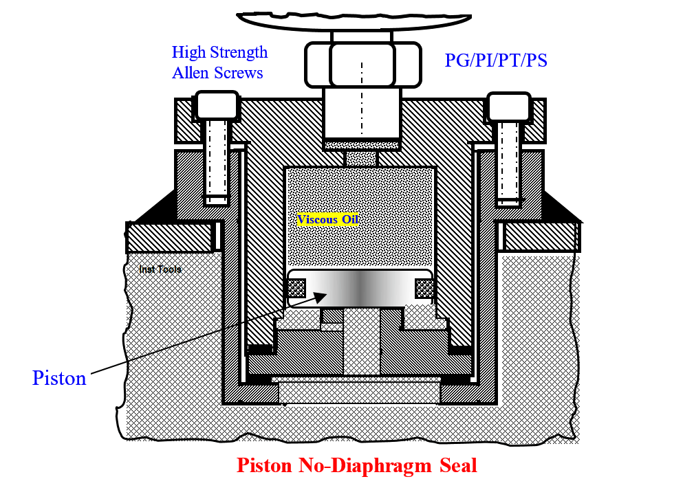
Piston No-Diaphragm Seals (PNDS)
(Fig 8): while writing this article the below described PNDS flashed to the author:
Remove the pinholes developed diaphragm from seal body and modify according to fig 8.
Machine SS piston for 0.5 mm clearance with the 0.4µm RMS smooth finished bore and fit PTFE filled rope packing in the piston groove.
Fill viscous oil above piston. Screw in PI/PT/PS/PG to the seal body. Piston seal instrument is ready for use.
Readers can make flanged PNDS also along these lines.
Advantages of Piston No-Diaphragm Seals
Piston No-Diaphragm Seals (PNDS) foreseen advantages as follows:
- Diaphragm and its consequent problems are absent. Hence, a really fit and forget device
- Minimum easy modification for both body and flange seal of horizontal and vertical pipelines
- Especially useful for applications where suitable Seal liquid is not available
Since, the author is no longer in service, he requests seal PI/PT/PS/PG problems overwhelmed readers to try out the piston seal and pass on feedback to him.
The author is sure of its success after identifying and removing ‘bugs’ if any seen.
Author: S. Raghava Chari
Do you face any similar issues? Share with us through the below comments section.
If you liked this article, then please subscribe to our YouTube Channel for Instrumentation, Electrical, PLC, and SCADA video tutorials.
You can also follow us on Facebook and Twitter to receive daily updates.
Read Next:
- Actuator Diaphragm Bursts
- Thermocouple Extension Leads
- Pitot-tube Replaced with Orifice
- Mechanical Temperature Indicator
- Pressure Transmitter Stopped Working