The field instrumentation in process plants is beginning to come under more sophisticated metrological discipline. Most new field instruments are now smart digital instruments. One popular digital protocol is the HART (Highway Automated Remote Transducer) protocol, which shares characteristics of both analog and digital control systems.
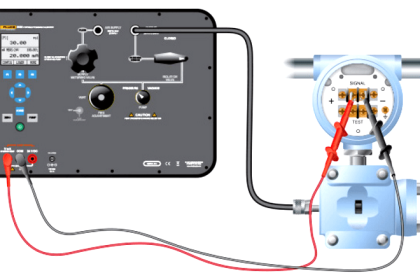
To properly service these instruments, precision analog source / measure capability and digital communication are both required. Historically, this operation has required two separate tools, a calibrator and a communicator. Today, these capabilities are available in a single HART Process Calibrator that can help technicians quickly and effectively service a HART instrument workload.
What is HART protocol ?
HART stands for Highway Addressable Remote Transducer.
The HART protocol uses 1200 baud Frequency Shift Keying (FSK) based on the Bell 202 standard to superimpose digital information on the conventional 4-20 mA analog signal. Maintained by an independent organization, the HART Communication Foundation, the HART protocol is an industry standard developed to define the communications protocol between intelligent field devices and a control system.
HART is the most widely used digital communication protocol in the process industries, with over five million HART field instruments installed in over 100,000 plants worldwide.
HART Protocol:
- Is supported by all of the major vendors of process field instruments
- Preserves present control strategies by allowing traditional 4-20 mA signals to co-exist with digital communication on existing two-wire loops
- Is compatible with traditional analog devices
- Provides important information for installation and maintenance, such as Tag-IDs, measured values, range and span data, product information and diagnostics
- Can support cabling savings through use of multidrop networks
- Reduces operation costs, through improved management and utilization of smart instrument networks
How are HART instruments calibrated?
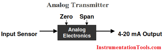
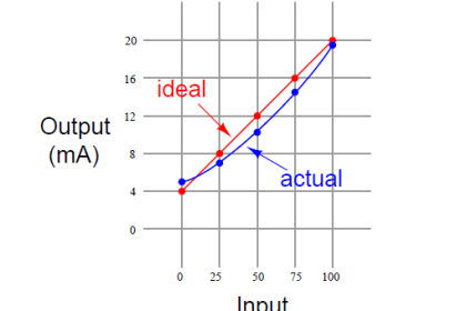
Calibration of an analog transmitter is fairly straightforward. Following an As-Found test, the zero and span adjustments may be used to set the correct relationship between the input signal and the 4 – 20 mA output. An As-Left test completes the calibration.
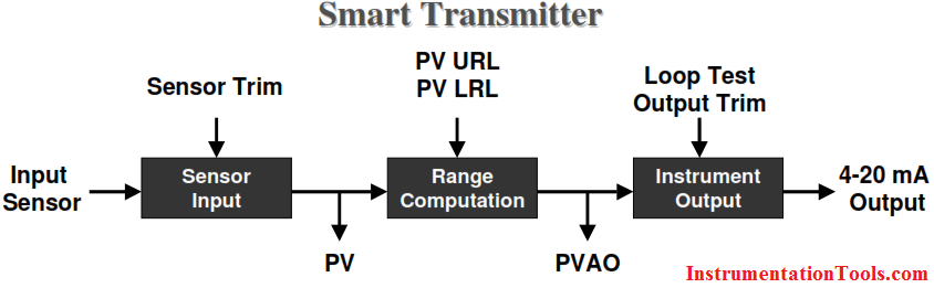
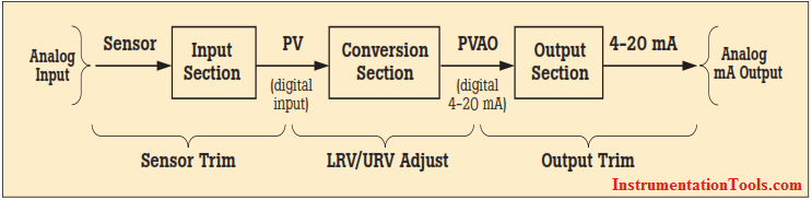
A HART instrument is more complex, having three distinct stages. The sensor input stage sets the relationship between an input sensor and the PV, or primary variable. The PV is denominated in engineering units, for example, psi or oF. The Sensor Input stage is adjusted by digitally trimming using Sensor Trim.
The second stage is a computational stage, establishing the relationship between PV (Primary Variable) and PVAO (Primary Variable Analog Output). Range is scaled by assigning the PV Upper Range Limit and Lower Range Limit values. The PVAO is a digital value of the 4-20 mA output signal.
The final stage, the Instrument Output, is set digitally with Output Trim. Performing these trims and entering the URV and LRV has typically been performed using a HART configurator or communicator. A separate calibrator was required to provide the precision analog source and measure functions.
The calibration approach for a HART instrument will depend on how the transmitter outputs are used. If only the 4-20 mA analog signal is used, it may be treated much as an analog transmitter. Using the manual zero and span buttons on the transmitter, or by digitally setting the PV LRV and PV URV, the correct relationship between input sensor and 4-20 mA analog output are set.
However, in this scenario, the Sensor Input stage has not been properly adjusted. If one were to use a communicator to read the digital value PV, it will most likely be incorrect, even though the 4-20 mA output will be correct.
If any of the digital signals will be used by the control system, then a more rigorous approach is required. If the PV will be used, then the input stage must be correctly set using Sensor Trim. Then the PV LRV and PV URV should be digitally assigned, and never changed using the manual zero and span buttons. Finally, the Output Trim is used to correctly set the relationship between the PVAO and the 4-20 mA analog output.
is HART calibration required :
A common misconception is that the accuracy and stability of HART instruments eliminate the need for calibration. Another misconception is that calibration can be accomplished by re-ranging field instruments using only a HART communicator. Still another misconception is that the control system can remotely calibrate smart instruments. These are not true. All instruments drift. Re-ranging with just a communicator is not calibration.
A precision calibrator or standard is required. Regular performance verification with a calibrator traceable to national standards is necessary due to:
- Shifts in performance of electronic instruments over time, due to exposure of the electronics and the primary sensing element to temperature, humidity, pollutants, vibration, and other field environmental factors.
- Regulations governing occupational safety, consumer safety, and environmental protection.
- Quality programs such as ISO 9000 standards for all instruments that impact product quality.
- Commercial requirements such as weights, measures, and custody transfer. Regular calibration is also prudent since performance checks will often uncover problems not directly caused by the instrumentation, such as solidified or congealed pressure lines, installation of an incorrect thermocouple type, or other errors and faults.
A calibration procedure consists of a verification (As Found) test, adjustment to within acceptable tolerance if neces sary, and a final verification (As Left) test if an adjustment has been made. Data from the calibration are collected and used to complete a report of calibration, documenting instrument performance over time.
All instruments, even HART instruments, must be calibrated on a regular, preventive maintenance schedule. The calibration interval should be set short enough to insure that an instrument never drifts out of tolerance, yet long enough to avoid unnecessary calibrations. Alternatively, the interval may be determined by critical process requirements, e.g., calibration before each batch.
Also Read: HART Communication Interview Questions & Answers


I really appreciate the work your doing. I am in 3rd year of instrumentation and control but still i believe i dont have much knowledge in this field. You website is very much helpful in explaining the concepts clearly. Please do continue this work and share it. You are doing a great work. Thanks
Ur work is very very grateful knowledge. Do continue
Good work..All in one package..thanks
Dear Sir,
Small correction :
HART: HIGHWARY ADDRESSABLE REMOTE TRANSDUCER
Hello Mahendra, HART Communications Protocol (Highway Addressable Remote Transducer). Plz Re-Check. Thank You.
good job sir
what is druck??
how can I calibrate a PDE310 Precision Digital Hart instrument
I have 6 of them displaying 6 deg or more out of tollerence