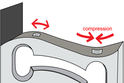
Most pneumatic instruments use a simple but highly sensitive mechanism for converting mechanical motion into variable air pressure: the baffle-and-nozzle assembly (sometimes referred to as a flapper and- nozzle assembly). A baffle is nothing more than a flat object obstructing the flow of air out of a small nozzle by close proximity:
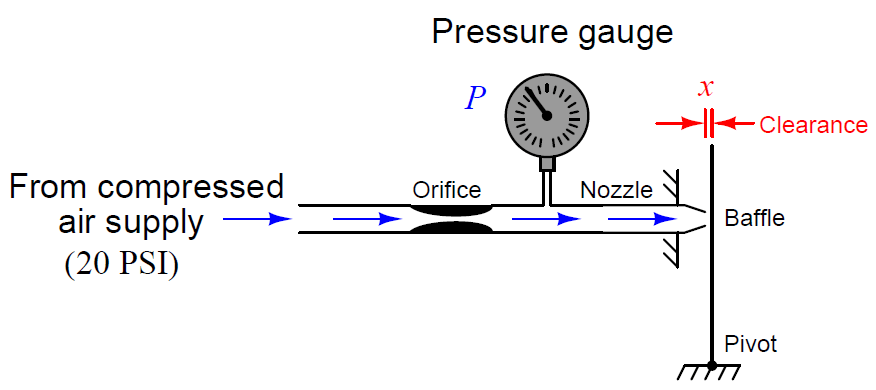
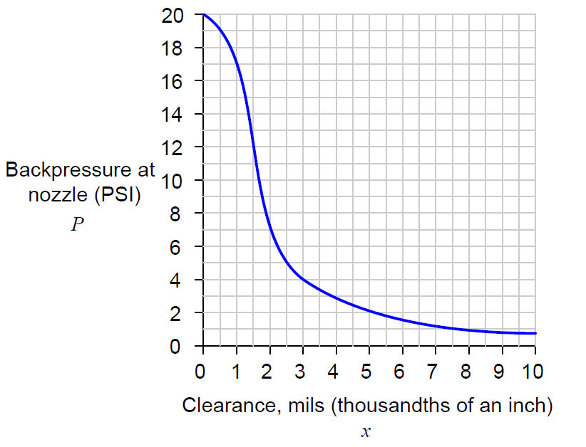
The physical distance between the baffle and the nozzle alters the resistance of air flow through the nozzle. This in turn affects the air pressure built up inside the nozzle (called the nozzle back-pressure). Like a voltage divider circuit formed by one fixed resistor and one variable resistor, the baffle/nozzle mechanism “divides” the pneumatic source pressure to a lower value based on the ratio of restrictiveness between the nozzle and the fixed orifice.
This crude assemblage is surprisingly sensitive, as shown by the graph. With a small enough orifice, just a few thousandths of an inch of motion is enough to drive the pneumatic output between its saturation limits. Pneumatic transmitters typically employ a small sheet-metal lever as the baffle. The slightest motion imparted to this baffle by changes in the process variable (pressure, temperature, flow, level, etc.) detected by some sensing element will cause the air pressure to change in response.
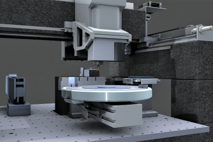
The principle behind the operation of a baffle/nozzle mechanism is often used directly in quality control work, checking for proper dimensioning of machined metal parts. Take for instance this shaft diameter checker, using air to determine whether or not a machined shaft inserted by a human operator is of the proper diameter after being manufactured on an assembly line:
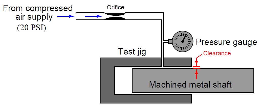
If the shaft diameter is too small, there will be excessive clearance between the shaft and the inside diameter of the test jig, causing less air pressure to register on the gauge. Conversely, if the shaft diameter is too large, the clearance will be less and the gauge will register a greater air pressure because the flow of air will be obstructed by the reduced clearance.
The exact pressure is of no particular consequence to the quality-control operator reading the gauge. What does matter is that the pressure falls within an acceptable range, reflecting proper manufacturing tolerances for the shaft. In fact, just like the 3-15 PSI “receiver gauges” used as pneumatic instrument indicators, the face of this pressure gauge might very well lack pressure units (such as kPa or PSI), but rather be labeled with a colored band showing acceptable limits of mechanical fit:
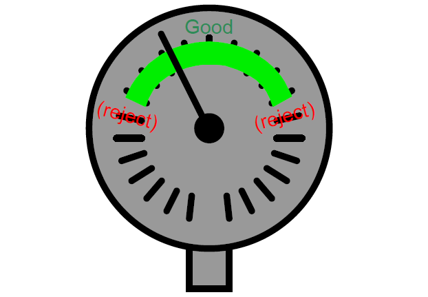 This is another example of the analog nature of pneumatic pressure signals: the pressure registered by this gauge represents a completely different variable, in this case the mechanical fit of the shaft to the test jig.
Although it is possible to construct a pneumatic instrument consisting only of a baffle/nozzle mechanism, this is rarely done. Usually the baffle/nozzle mechanism is just one of several components comprising a “balancing” mechanism in a pneumatic instrument. It is this concept of self-balancing that we will study next.