Inst ToolsInst ToolsInst Tools
  • Courses
  • Automation
    • PLC
    • Control System
    • Safety System
    • Communication
    • Fire & Gas System
  • Instrumentation
    • Design
    • Pressure
    • Temperature
    • Flow
    • Level
    • Vibration
    • Analyzer
    • Control Valve
    • Switch
    • Calibration
    • Erection & Commissioning
  • Interview
    • Instrumentation
    • Electrical
    • Electronics
    • Practical
  • Q&A
    • Instrumentation
    • Control System
    • Electrical
    • Electronics
    • Analog Electronics
    • Digital Electronics
    • Power Electronics
    • Microprocessor
Search
  • Books
  • Software
  • Projects
  • Process
  • Tools
  • Basics
  • Formula
  • Power Plant
  • Root Cause Analysis
  • Electrical Basics
  • Animation
  • Standards
  • 4-20 mA Course
  • Siemens PLC Course
Reading: Remote Seal Transmitters Temperature Error
Share
Notification Show More
Font ResizerAa
Inst ToolsInst Tools
Font ResizerAa
  • Courses
  • Design
  • PLC
  • Interview
  • Control System
Search
  • Courses
  • Automation
    • PLC
    • Control System
    • Safety System
    • Communication
    • Fire & Gas System
  • Instrumentation
    • Design
    • Pressure
    • Temperature
    • Flow
    • Level
    • Vibration
    • Analyzer
    • Control Valve
    • Switch
    • Calibration
    • Erection & Commissioning
  • Interview
    • Instrumentation
    • Electrical
    • Electronics
    • Practical
  • Q&A
    • Instrumentation
    • Control System
    • Electrical
    • Electronics
    • Analog Electronics
    • Digital Electronics
    • Power Electronics
    • Microprocessor
Follow US
All rights reserved. Reproduction in whole or in part without written permission is prohibited.
Inst Tools > Blog > Instrumentation Design > Remote Seal Transmitters Temperature Error

Remote Seal Transmitters Temperature Error

Last updated: August 11, 2019 12:18 pm
Editorial Staff
Instrumentation Design
1 Comment
Share
3 Min Read
SHARE

Calculation of temperature error for remote seals

The following equation is used to calculate the temperature error for remote seals:

Contents
Calculation of temperature error for remote sealsExample of calculation of temperature error for remote sealsMeasuring errors based on physical properties always result when using remote sealsDependence of temperature error on diaphragm material

dp = (tRS – tCal) . fRS + (tCap – tCal) . lCap . fCap + (tTR – tCal) . fPF

Where

  • dp – Additional temperature error (inH2O)
  • tRS – Temperature on remote seal diaphragm (generally corresponds to temperature of medium)
  • tCal – Reference (calibration) temperature 68 °F
  • fRS – Temperature error of remote seal
  • tCap – Ambient temperature on the capillaries
  • ICap – Capillary extension length (error given per 3 ft)
  • fCap – Temperature error of capillaries
  • tTR – Ambient temperature on transmitter
  • fPF – Temperature error of oil filling in process flanges of transmitter

Example of calculation of temperature error for remote seals

Existing conditions:

  • Remote Seal type DP Transmitter, fRS = 0.054 inH2O/25 °F
  • Capillary ICap = 2 x 15 ft
  • Capillaries fitted on both sides, fCap= 0.042 inH2O/25 °F/3 ft
  • Filled with silicone oil DC 200-10, fPF = 0.042 inH2O/25 °F
  • Temperature of medium 212 °F, tRS = 212 °F
  • Temperature on capillaries 122 °F, tCap = 122 °F
  • Temperature on transmitter 122 °F, tTR = 122 °F

Required:

  • Additional temperature error of remote seal: dp

Calculation:

dp = (212 °F – 68 °F) . 0.077 inH2O/25 °F + (122 °F – 68 °F) . 15 ft . 2 . 0.042 inH2O/25 °F / 3ft + (122 °F – 68 °F) . 0.042 inH2O/25 °F

dp = 0.444 inH2O + 0.907 inH2O + 0.091 inH2O

Result:

dp = 1.442 inH2O (corresponds to 3.605 % of set span)

Note:

The temperature error determined above only applies to the error resulting from connection of the remote seal.

The transmission response of the respective transmitter is not included in this consideration. It must be calculated separately, and the resulting error added to the error determined above from connection of the remote seal.

Measuring errors based on physical properties always result when using remote seals

Temperature errors of diaphragm seals when connected to pressure, absolute pressure or level transmitters, and with single-sided connection to differential pressure transmitters
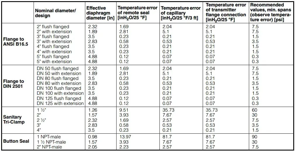
Temperature errors of diaphragm seals

Remarks:

  • Values apply to fill fluid: silicone oil DC 200, high-temperature oil, halocarbon oil and Neobee M20.
  • Values apply to stainless steel as the diaphragm material.

Dependence of temperature error on diaphragm material

The errors listed in the tables on pages 2/140 and 2/141 refer to the use of stainless steel as the diaphragm material. If a different material is used, the listed values change by the amount shown in the following table.
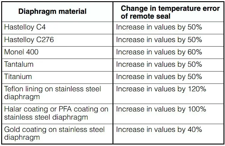
Dependence of temperature error on diaphragm material

Source : Siemens

Don't Miss Our Updates
Be the first to get exclusive content straight to your email.
We promise not to spam you. You can unsubscribe at any time.
Invalid email address
You've successfully subscribed !

Continue Reading

Instrumentation Role during Steam Blowing
Flow Instruments – Selection, Principle & Application
What to Choose RTD or Thermocouple ?
Basic Requirements of Control Valves Sizing
What is SAMA Diagram?
Motor Control Center (MCC) Signal Interface Termination (SIT)
Share This Article
Facebook Whatsapp Whatsapp LinkedIn Copy Link
Share
1 Comment
  • Prashant Srivastava says:
    July 9, 2019 at 8:27 pm

    kindly explain the diaphragm material used in which kind of fluid. ie hydrogen, chlorine, acid, brine, steam/water etc.

    Reply

Leave a Reply Cancel reply

Your email address will not be published. Required fields are marked *

Stay Connected

128.3kFollowersLike
69.1kFollowersFollow
208kSubscribersSubscribe
38kFollowersFollow

Categories

Explore More

Pneumatic Valves and Cylinders Sizing – Part 1
Single and Three Phase Immersion Electrical Heaters Wiring Circuits
Instrumentation Books Download
How-to Create Instrument Loop Diagram (ILD)?
What is Instrument DataSheet ?
Pull Up and Pull Down Switch Circuits
Air Cylinder Consumption Calculation for Control Valves
Pressure Control Valves vs Pressure Regulators

Keep Learning

Temperature Gauges and Elements Specifications

Temperature Gauges and Elements : Detailed Specifications

Poppet vs Spool Valves

Why Valve Type Matters ? Poppet vs Spool Valves

float-type level switch control a pump

Float-type Level Switch to Control a pump

Important Factors Consider during Piping Design

Important Factors Consider during Piping Design

Control Room Design Guidelines

Control Room Design Guidelines

Top 10 Facts about HART Technology

Top 10 Facts about HART Technology

Temperature Sensor Failure

Temperature Sensor Failure

Readings Mismatch between Field & Control Room

Readings Mismatch between Field & Control Room ? Why

Learn More

Volume Booster Working Principle

Control Valve Volume Booster Working Principle

Siemens CPU Clock Memory

Alarm Acknowledge using PLC

Instrument Air (IA) System

Process Design of Instrument Air System

PLC Program for Fishpond Water Level Monitoring System

PLC Program for Artificial Fishpond Water Level Monitoring System

Temperature Measurement Objective Questions

Temperature Measurement Objective Questions

Parking Lights PLC Program Explained with Video

Parking Lights PLC Program Explained with Video

Direct operated (direct acting) solenoid valves

Solenoid Valves Types & Functions

Dissolved oxygen measurement using Optical Fiber Communication

Fiber Optic Sensors

Follow US
All rights reserved. Reproduction in whole or in part without written permission is prohibited.
Welcome Back!

Sign in to your account

Username or Email Address
Password

Lost your password?