Inst ToolsInst ToolsInst Tools
  • Courses
  • Automation
    • PLC
    • Control System
    • Safety System
    • Communication
    • Fire & Gas System
  • Instrumentation
    • Design
    • Pressure
    • Temperature
    • Flow
    • Level
    • Vibration
    • Analyzer
    • Control Valve
    • Switch
    • Calibration
    • Erection & Commissioning
  • Interview
    • Instrumentation
    • Electrical
    • Electronics
    • Practical
  • Q&A
    • Instrumentation
    • Control System
    • Electrical
    • Electronics
    • Analog Electronics
    • Digital Electronics
    • Power Electronics
    • Microprocessor
  • Request
Search
  • Books
  • Software
  • Projects
  • Process
  • Tools
  • Basics
  • Formula
  • Power Plant
  • Root Cause Analysis
  • Electrical Basics
  • Animation
  • Standards
  • 4-20 mA Course
  • Siemens PLC Course
Reading: Flanged Rotameter Caused Pipe Weld Cracks and Gives Wrong Readings
Share
Notification Show More
Font ResizerAa
Inst ToolsInst Tools
Font ResizerAa
  • Courses
  • Design
  • PLC
  • Interview
  • Control System
Search
  • Courses
  • Automation
    • PLC
    • Control System
    • Safety System
    • Communication
    • Fire & Gas System
  • Instrumentation
    • Design
    • Pressure
    • Temperature
    • Flow
    • Level
    • Vibration
    • Analyzer
    • Control Valve
    • Switch
    • Calibration
    • Erection & Commissioning
  • Interview
    • Instrumentation
    • Electrical
    • Electronics
    • Practical
  • Q&A
    • Instrumentation
    • Control System
    • Electrical
    • Electronics
    • Analog Electronics
    • Digital Electronics
    • Power Electronics
    • Microprocessor
  • Request
Follow US
All rights reserved. Reproduction in whole or in part without written permission is prohibited.
Inst Tools > Blog > Root Cause Analysis (RCA) > Flanged Rotameter Caused Pipe Weld Cracks and Gives Wrong Readings

Flanged Rotameter Caused Pipe Weld Cracks and Gives Wrong Readings

Heavy 4” 300# flanged rotameter not only gives wrong readings but also caused pipe weld cracks in the process plant.

Last updated: September 28, 2022 2:55 pm
S Raghava Chari
Root Cause Analysis (RCA)
No Comments
Share
6 Min Read
SHARE

Heavy 4” 300# flanged rotameter not only gives wrong readings but also caused pipe weld cracks in the process plant.

Contents
Flanged Rotameter ProblemsAuthor RCA SolutionRCA solution benefitsAlternative for the Rotameter Flow Meter
Article Type:Root Cause Analysis (RCA)
Category:Instrumentation
Equipment Type:Sensors
Author:S. Raghava Chari

Note: This root cause analysis (RCA) is from real-time scenarios that happened in industries during the tenure of two or three decades ago. These articles will help you to improve your troubleshooting skills and knowledge.

Flanged Rotameter Problems

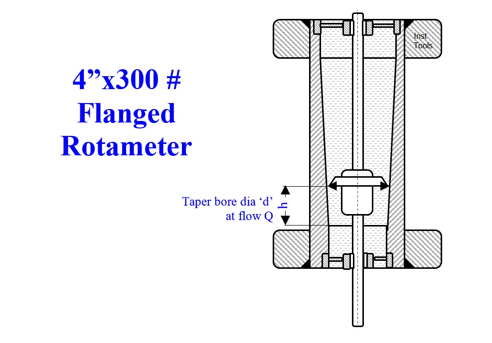
Rotameter Information: Fig 1 shows a 4” flanged rotameter. The rotameter inlet bore tapers to a larger dia at the exit. Table 1 lists its data:

Table 1; Typical 4” Rotameter Data

h (mm)MBR (mm)Q (m3/H)C – Q/h (ratio)
500.0010028275.65
475.0099.0026715.62
356.2594.2619525.48
237.5089.612795.38
118.7584.756155.18
0.00800.000.00
h-Graduation distance from zero flow; MBR-Meter body bore dia; Flow rate Q;

Table 1 shows that the rotameter scale is nearly linear. The plunger pump delivered flow stream velocity varies instant to instant and hence the float assumes a position representing the instantaneous flow rates average depending upon the float’s mass and the flow stream viscosity.

Hence, rotameters read pulsating flows a lot more accurately than square root scale receivers connected to Differential Pressure Transmitters (DPTs) across orifice plates, because, the DPT measured

hav = (h1+h2+h3+ … hn)/n

where

h1, h2, and h3, are the instantaneous differential pressures across the orifice plate.  The receiver’s square root scale square root scale reads the above shown √aaverage.

But the receiver must actually read √hc = (√h1+√h2+√h3+ … √hn)/n. These two averages may differ as much as 50% depending upon the type of machine delivering the pulsating flows and the orifice upstream pipelines’ and vessels’ volumes sum.

Electronic DPTs calibrated to output √h signals are also free from this error. 

Problem:  The carbomate pump suction pipe bolted body clamped pneumatic transmitter 4” 300# flanged SS rotameter though capable of reading the pump delivered flow roughly accurately, always read very wrong. The reasons are:

The Plunger pump delivered flow pulsations generally shake the connected piping way high; the rotameter upstream, downstream and the bypass 4”x300# heavy plug valves aggravated the pipeline’s vibrations much more.

Flange Rotameter

Hence, the pipelines’ added welds for the rotameter and its bypass installation cracked and shutdown the plant often at enormous production loss

  1. The shaking pipes shook transmitter’s delicate flapper made the flow transmitter outputs and hence the receiver readings totally meaningless
  2. Often the instrument parts broke and involved excessive instrument crew efforts in a ‘no-use’ flow measurement of very poor availability
  3. Inability to hold the rotameter exactly vertical added to these problems
  4. Perennial Jacket steam leaks posed steam loss and housekeeping problems 

Author RCA Solution

The author highlighted the worthless rotameter system posed plant shutdowns. Operations too tired of the plant shutdowns, which loaded them heavily besides lost production, reluctantly agreed the rotameter and bypass valves temporary removal, on the author agreeing to find better flow metering methods, Eventually, they forgot the flow measurement that served no purpose!      

RCA solution benefits

RCA solution benefits are:

  1. The simple rule is ‘no welds’ no shakes caused welds cracks; hence the rotameter and its bypass elimination eliminated the perpetually recurring pipelines welds cracks caused lengthy plant shutdowns

Thanks to far higher on stream hours, far higher production and far reduced workload, the operation crew eventually did not ask for  the no-use rotameter

Alternative for the Rotameter Flow Meter

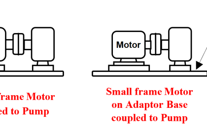
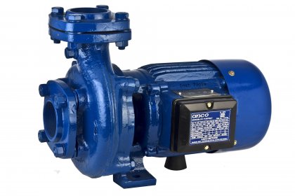
Long after the rotameter removal, the author thought of an alternative for the rotameter: each of the carbomate pumps has Fig 2 RPM indicator: the Pulse to I converter powered a speed probe views the pump shaft key and sends electrical pulses/sec signal proportional to the pump RPM to the pulse to I convertor.

Pump RPM Controller

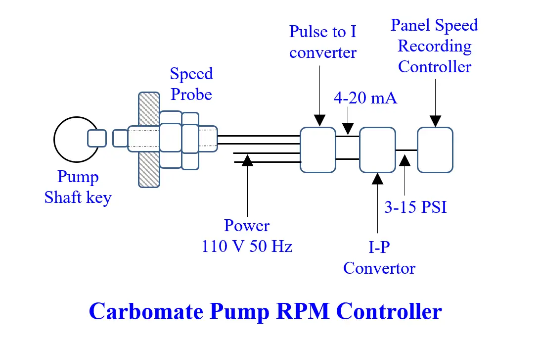
An I-P converter renders the pulse to the I convertor’s 4-20 mA output into 3-15 psi signals for the panel mounted ‘Speed Recording Controllers (SRC)’ which pull/push the hydraulic torque convertors’ internal vanes angle adjusting rod to vary the pump RPM.

The author could have easily added pump delivered m3/H graduations to the SRCs’ pump RPM scales in a different color as the plunger pumps’ delivered flow

Q = 3*N*S*0.25πd^2*l where

SymbolDescription
QPump delivered flow m3/min
3Each pump’s Number of plungers
NPump RPM
dPlunger dia m
lStroke Length m

The operation engineers forgot the flow measurement and the more pressing other work pressured the author too!

Author: S. Raghava Chari

Do you face any similar issues? Share with us through the below comments section.

If you liked this article, then please subscribe to our YouTube Channel for Instrumentation, Electrical, PLC, and SCADA video tutorials.

You can also follow us on Facebook and Twitter to receive daily updates.

Read Next:

  • Level Transmitters Zero Drifts
  • Target Flow Transmitters Failed
  • Pitot-tube Replaced with Orifice
  • Mechanical Temperature Indicator
  • Seal Pressure Instruments Problems
Don't Miss Our Updates
Be the first to get exclusive content straight to your email.
We promise not to spam you. You can unsubscribe at any time.
Invalid email address
You've successfully subscribed !

Continue Reading

11 KV Bus A to Bus B Phase Check Problem
Plant Air Storage Tank Pressure Fluctuations Root Cause Analysis
Erratic Stroking Control Valves Delaying the Shutdown Plant Restart
Cooling Tower fan FRP fan blades saves and saves
Arc Fault Breaker (AFB) Electrical Problem Solved
Reformer Fan Bearing Change Times cut by 90%
Share This Article
Facebook Whatsapp Whatsapp LinkedIn Copy Link
Share
Leave a Comment

Leave a Reply Cancel reply

Your email address will not be published. Required fields are marked *

Stay Connected

128.3kFollowersLike
69.1kFollowersFollow
210kSubscribersSubscribe
38kFollowersFollow

Categories

Explore More

Finned Tube Steam Leaks – Root Cause Analysis
Seawater Pipeline Spools from day-1 leaks threaten Plant Shutdown
An Indian Plants all turbines’ low Vacuum & Saudi Plant turbo-compressor only
Control Valves – Repeat Actuator Diaphragm Bursts
HT Motor Problem appears after Disassembly and Reassembly
Mechanical Engineering Plant Problems Solved – Root Cause Analysis
Captive Power Plant Trip Root Cause Analysis
Incident Investigation: Motor Operated Valve Lesson

Keep Learning

Plant Shutdown Analysis: Valve Closed and SOV Coil Failure

Plant Shutdown Analysis: Valve Closed and SOV Coil Failure

On Off Valve Root Cause Analysis

Root Cause Analysis for FRP Line Damaged due to On-Off Valve

Modern Cement Kiln Drive

Cement kilns, Rotary Drum Driers Simplest Electrical Drive

Minimum Oil Circuit Breaker (MOCB) Spares & Service

Minimum Oil Circuit Breaker (MOCB) No Vendor Spares & Service

Mechanical Temperature Indicators (MTI) Problem

Mechanical Temperature Indicators (MTI) Problem

Fasteners and General Corrosion of Electrical Motors

Fasteners and General Corrosion of Electrical Motors

Butterfly Valve Failure caused Fire

Butterfly Valve Failure Caused Serious vicinity Heavy Fire

Flash Vessel All Level Instruments Stopped Working

Ammonia Flash Vessel All Level Instruments Stopped Working

Learn More

conductivity instruments

Four Electrode Conductivity Probes Principle

PLC FBD Example for Tank Liquid Heating Control by Steam Flow

PLC FBD Example for Tank Liquid Heating Control by Steam Flow

Phase Controlled Half Wave Rectifier RL Load

Power Electronics – Phase Controlled Half Wave Rectifier RL Load

Instrumentation Engineers Interview Questions & Answers

Instrumentation Engineers Interview Questions & Answers

Pressure Gauge Accessories

Pressure Gauge Accessories

Parallel Operation of Alternators

Difference between Single-phase and three-phase power supply

Difference between Single-phase and Three-phase Power

How is Data Stored in Standard Modbus Protocol?

How is Data Stored in Standard Modbus Protocol?

Menu

  • About
  • Privacy Policy
  • Copyright

Quick Links

  • Learn PLC
  • Helping Hand
  • Part Time Job

YouTube Subscribe

Follow US
All rights reserved. Reproduction in whole or in part without written permission is prohibited.
Welcome Back!

Sign in to your account

Username or Email Address
Password

Lost your password?