Root Cause Analysis (RCA): 50% only heat transferring from Heat Exchanger threatens urea plant commissioning indefinite halt.
Note: This root cause analysis (RCA) is from real-time scenarios that happened in industries during the tenure of one or two decades ago. These articles will help you to improve your troubleshooting skills and knowledge.
Heat Exchanger Root Cause Analysis
A high-pressure U-tube heat exchanger (HE) exiting stream too high temperature halted a urea plant commissioning and baffled everyone.
Calculations showed the heat exchanger transfers nearly ½ the rated heat transfer only. Even a new exchanger receivable 9 months later only may not solve the problem, unless someone finds and removes the ½ heat transfer cause.
An immediate remedy was necessary to make the exchanger work to design soonest for commissioning completion and urea production start.
Several shell pullouts revealed no flaws baffled everyone. Each time the crew carefully supported the tube bundle by placing wooden sleepers at the baffle locations to avoid tube bundle sag and associated tube cracks.
The plant manager ordered to leave the heat exchanger dissembled hoping a solution for this Difficult to Diagnose, Unusual Despairing, Problem (DDUDP) – the plant name for such problems – may flash to someone.
RCA Queries and Response
An inspection engineer had a flash! He reviewed the heat exchanger drawing and root caused analyzed as below; Q-RCA queries and R – response:
Query 1
Q: Why ½ heat transfer duty only?
R: Maybe water flows in ½ heat transfer area only
Query 2
Q: Why so?
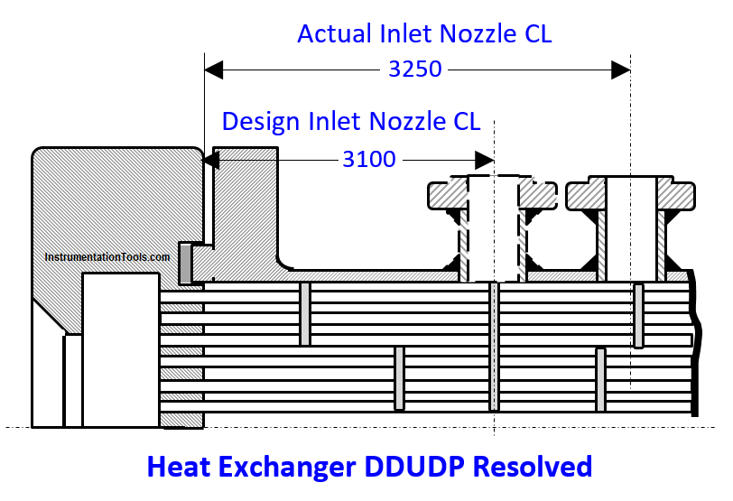
R: Several minutes thought and repeated drawing studies flashed response was: maybe the inlet water nozzle CL is not at the full baffle plate CL (above figure) – a fabrication mistake. In that case cooling water flows in ½ the exchanger and negligible in the other half; hence ½ heat transfer!
Query 3
Q: How to verify?
R: Below are several minutes thought and few drawing studies suggested wayout:
- Measured full baffle CL distance from channel head tip 3100 mm
- Measured nozzle CL distance from shell flange raised face tip 3250 mm
- Above 1 and 2 measurements are necessary because the heat exchanger manual shows a sketch with outline dimensions only.
- Above 1 and 2 measurements and ignoring the negligible measuring errors indicate the nozzle CL is 150 mm away from where it should be
- Welding the nozzle at the correct location would solve the DDUDP
DDUDP solved!
The inspection engineer guided, a mill wright and welder team marked the nozzle new location (above figure), flame cut a 170 mm dia – 6” Nozzle OD – opening, saved the disc, flame cut the inlet water nozzle, welded it at the new opening and blinded the left out opening welding the saved disc. As the shell handles 3 bars CW only the welds are not that critical.
That team aided by a rigger cello taped a new gasket to the channel head gasket groove, pushed the shell in and bolted it to the channel head. In addition, they connected the inlet water pipe to the inlet nozzle – minor pipe line change job.
Operation crew put the exchanger in service and reported it performing better than design.
RCA Solution Benefits
- Avoided shutting down the commissioned and well running upstream NH3 plant; in turn avoided cancelling the committed natural gas (NG) purchase orders at enormous cancellation charges
- Avoided the NH3 plant’s moth balling very high costs
- Avoided committed urea non-delivery high penalties
- Avoided many other costs
- The threatened indefinite delay reduced to just a day
- Crews and supervisors gained confidence to tackle any future DDUDPs
- The plant saved astronomical money sums by starting urea production and fulfilling the committed orders and built a high image as a dependable urea supplier.
Author: S. Raghava Chari
Do you face any similar issues? Share with us through the below comments section.
If you liked this article, then please subscribe to our YouTube Channel for Instrumentation, Electrical, PLC, and SCADA video tutorials.
You can also follow us on Facebook and Twitter to receive daily updates.
Read Next:


Kindly share more information on Difficult to Diagnose, Unusual Despairing, Problem (DDUDP) methodology.
Regds
Avinash Shinde
Century enka Ltd.
Dear Avinash,
I thought the readers including you would have learnt the DDUDP solving methodology themselves from my description of how I solved so many of my DDUDPs: just follow the root cause analysis techniques: first get the subject in depth knowledge, e.g., in case of antifriction bearing problems, get in depth AFB knowledge from an AFB catalog study.
You will find, many of the AFB problems I solved remained unsolved for over 10 years, because knowhow lacking crews too tight fitted the AFBs, and their spurious AFBs mindset, prevented root cause analysis. Always, ensure the process operates at close to design conditions, e.g., see the case study of popping relief valve and rupturing rupture discs. In short, good job knowledge application, no mindset and RCA are essential for DDUDP solving.