Inst ToolsInst ToolsInst Tools
  • Courses
  • Automation
    • PLC
    • Control System
    • Safety System
    • Communication
    • Fire & Gas System
  • Instrumentation
    • Design
    • Pressure
    • Temperature
    • Flow
    • Level
    • Vibration
    • Analyzer
    • Control Valve
    • Switch
    • Calibration
    • Erection & Commissioning
  • Interview
    • Instrumentation
    • Electrical
    • Electronics
    • Practical
  • Q&A
    • Instrumentation
    • Control System
    • Electrical
    • Electronics
    • Analog Electronics
    • Digital Electronics
    • Power Electronics
    • Microprocessor
  • Request
Search
  • Books
  • Software
  • Projects
  • Process
  • Tools
  • Basics
  • Formula
  • Power Plant
  • Root Cause Analysis
  • Electrical Basics
  • Animation
  • Standards
  • 4-20 mA Course
  • Siemens PLC Course
Reading: Indentify Faults in Simple Lamp Circuit including Failed Wires
Share
Font ResizerAa
Inst ToolsInst Tools
Font ResizerAa
  • Courses
  • Design
  • PLC
  • Interview
  • Control System
Search
  • Courses
  • Automation
    • PLC
    • Control System
    • Safety System
    • Communication
    • Fire & Gas System
  • Instrumentation
    • Design
    • Pressure
    • Temperature
    • Flow
    • Level
    • Vibration
    • Analyzer
    • Control Valve
    • Switch
    • Calibration
    • Erection & Commissioning
  • Interview
    • Instrumentation
    • Electrical
    • Electronics
    • Practical
  • Q&A
    • Instrumentation
    • Control System
    • Electrical
    • Electronics
    • Analog Electronics
    • Digital Electronics
    • Power Electronics
    • Microprocessor
  • Request
Follow US
All rights reserved. Reproduction in whole or in part without written permission is prohibited.
Inst Tools > Blog > Practical Questions > Indentify Faults in Simple Lamp Circuit including Failed Wires

Indentify Faults in Simple Lamp Circuit including Failed Wires

Last updated: June 9, 2020 12:25 pm
Editorial Staff
Practical Questions
No Comments
Share
3 Min Read
SHARE

Suppose the lamp refuses to light up. A voltmeter registers 24 volts between test points C and D:

Simple Lamp Circuit

Suppose the lamp refuses to light up

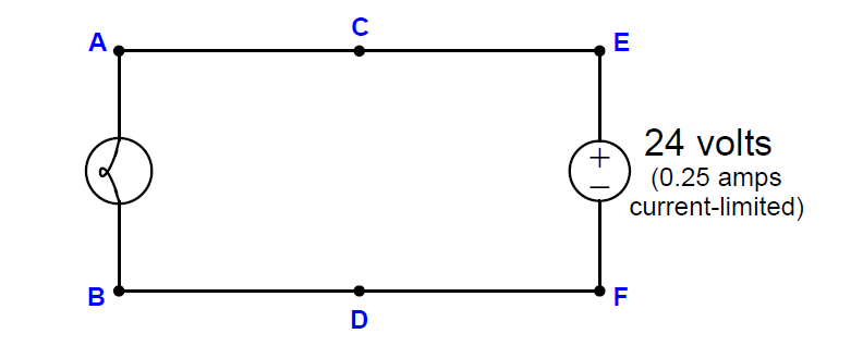
First, list all the possible (single) faults that could account for all measurements and symptoms in this circuit, including failed wires as well as failed components:

Now, determine the diagnostic value of each of the following tests, based on the faults you listed above. If a proposed test could provide new information to help you identify the location and/or nature of the one fault, mark “yes.” Otherwise, if a proposed test would not reveal anything relevant to identifying the fault (already discernible from the measurements and symptoms given so far), mark “no.”

  • Measure VCF
  • Measure VED
  • Measure VAB
  • Measure VAD
  • Measure VCB
  • Measure VEF
  • Measure current through wire connecting A and C
  • Jumper A and C together
  • Jumper B and D together
  • Jumper A and B together

Finally, develop a rule you may use when assessing the value of each proposed test, based on a comprehensive list of possible faults.

Answer:

Here is a comprehensive list of faults, each one individually capable of accounting for the symptom (no light) and the measurement of 24 volts between C and D:

  • Lamp burned out (failed open)
  • Wire failed open between A and C
  • Wire failed open between B and D

Based on this short list of possible faults – assuming only one of them is actually true – the value of each proposed test is as follows:

  • Measure VCF –> NO
  • Measure VED –> NO
  • Measure VAB –> YES
  • Measure VAD –> YES
  • Measure VCB –> YES
  • Measure VEF –> NO
  • Measure current through wire connecting A and C  –> NO
  • Jumper A and C together  –> YES
  • Jumper B and D together  –> YES
  • Jumper A and B together  –> NO

A good rule to apply when evaluating proposed tests is to ask the question: “Will this test give me the exact same result no matter which one of the possible faults is true?” If so, the test is useless. If not (i.e. the results would differ depending on which of the possible faults was true), then the test has value because it will help narrow the field of possibilities.

Read Next:

  • How to Test Pressure Switch?
  • Instrument Engineer Interview
  • Energize to Safe Loop
  • Tank Level Control in PLC
  • Solenoid Manual Override
Don't Miss Our Updates
Be the first to get exclusive content straight to your email.
We promise not to spam you. You can unsubscribe at any time.
Invalid email address
You've successfully subscribed !

Continue Reading

Liquid Flow Control Loop Controller Action
Pressure Level Transmitter Problems
Calculate the Temperature of 4 Wire RTD
Calculate Hydraulic System Fluid Pressure
Guided-wave Radar Asset Management Parameters
Surface-mounted Water Pump
Share This Article
Facebook Whatsapp Whatsapp LinkedIn Copy Link
Share
Leave a Comment

Leave a Reply Cancel reply

Your email address will not be published. Required fields are marked *

Stay Connected

128.3kFollowersLike
69.1kFollowersFollow
210kSubscribersSubscribe
38kFollowersFollow

Categories

Explore More

Calculate 0%, 50%, and 100% Calibration Points for ΔP transmitter
Programmable Logic Controller (PLC) Questions and Answers – 6
Loop Powered Pressure Transmitter
Which Tube has most Hydrostatic Pressure?
Programmable Logic Controller (PLC) Questions and Answers – 11
Identify Problem with Oily Water Filter Instrumentation
Calculate the Magnitude of Hydrostatic Pressure
Analytical Process Control Question

Keep Learning

measure the temperature of RTD

Measure the Temperature of the RTD

Sump Tank Level Transmitter

Problem with Sump Tank Level Transmitter

DP Transmitter Wet Leg Compensating Impulse Line

Questions on DP Transmitter Wet Leg Compensating Impulse Line

Flapper nozzle system

Flapper Nozzle Questions

Programmable Logic Controller (PLC) Questions and Answers – 9

PLC Program for Valves

PLC Pump Permissive Interlocks

Loop Diagram

PT Loop Diagram Faults

Differential Pressure Transmitter with 5 Way Manifold Valve

Differential Pressure Transmitter with 5 Way Manifold Valve

Learn More

thermal imaging instrument

Thermal Imaging Temperature Measurement

Particle Image Velocimetry (PIV) Principle

Particle Image Velocimetry (PIV) Principle

Twisted Pair Cable Noise Supression

Why We use Shielded Cable and Twisted Pair Cables ?

PLC program pushbutton switches

PLC Permissive for Motor Control

Industrial Instrumentation Questions & Answers

Industrial Instrumentation Questions & Answers

Digital Electronics MCQ

Digital Integrated Circuits Objective Questions – Part 1

Digital Electronics Multiple Choice Questions

Read Only Memory (ROM) Objective Questions – Part 3

current division Formula for Resistor Circuit

Current Division

Menu

  • About
  • Privacy Policy
  • Copyright

Quick Links

  • Learn PLC
  • Helping Hand
  • Part Time Job

YouTube Subscribe

Follow US
All rights reserved. Reproduction in whole or in part without written permission is prohibited.
Welcome Back!

Sign in to your account

Username or Email Address
Password

Lost your password?