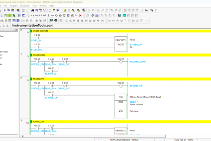
We prepared an article for industrial Automation Engineers Interview Questions and Answers.
Industrial Automation Engineers Interview Questions
1. What is Automation?
Automation is delegation of human control functions to technical equipment for increasing productivity, better quality, reduced cost & increased in safety working conditions.
2. What are the different components used in automation?
The components of automation system include
- Sensors for sensing the input parameters (RTD, Thermocouple, Pressure, Flow, Level; etc)
- Transmitters for transmitting the raw signal in electrical form
- Control system which includes PLC, DCS & PID controllers
- Output devices / actuators like drives, control valves.
3. What are the different control systems used in Automation?
- PID Controller based control system
- PLC based control system
- DCS based Control system
- PC Based automation system
4. Explain PID based control system.
PID (Proportional Integral Derivative) is the algorithm widely used in closed loop control.
The PID controller takes care of closed loop control in plant. A number of PID controller with single or multiple loop can be taken on network.
PID Controllers are widely for independent loops. Although some logic can be implemented but not much of sequential logic can be implemented in PIDs.
5. Difference between PLC & Relay ?
- PLC can be programmed whereas a relay cannot.
- PLC works for analog I/Os such as PID loops etc. whereas a relay cannot
- PLC is much more advanced as compared to relay.
- Modifications in relay base circuit is difficult compared to PLCs
6. Difference between PLC and DCS ?
DCS:
The system uses multiple processors, has a central database and the functionality is distributed. That is the controller sub system performs the control functions, the history node connects the data, the IMS node gives reports, the operator station gives a good HMI, the engineering station allows engineering changes to be made.
PLC:
The system has processor & I/O’s and some functional units like basic modules, communication modules and so on. Uses a SCADA for visualization. Generally the SCADA does not use a central database.
DCS is often used in the big plants where the redundancy level needed is more and the analog input used are high.
7. What is PC based control system ?
In PC based control system, the CPU of computer acts as processor, the PCI based cards are used for connecting Input and Output. The RAM acts as memory. Hard disk is used as storage device.
Currently this systems are very useful when the large data is to be proceed with very high speed. In many cases for greater accuracy we can use the real-time operating system.
8. What is Encoder ?
A feedback device which converts mechanical motion into electronic signals. Usually an encoder is a rotary device that outputs digital pulses which correspond to incremental angular motion.
The encoder consists of a glass or metal wheel with alternating clear and opaque stripes that are detected by optical sensors to produce the digital outputs.
9. Which are the leading PLC providers ?
The leading PLC providers include
- Rockwell Automation : Allen Bradley (Micrologix, SLC, PLC, Control Logix)
- Siemens ( S7 200, S7 300 , S7 400)
- Grouppe Schneider : Modicon ( Nano, Micro, Premium, Quantum)
- GE Fanuc : Versa, Series 90-30, 90-70
- Messung : Nextgen
10. Which are the leading DCS providers ?
The leading DCS providers include
- Yokogawa : Centum VP, CS 3000 , CS 5000 (Earlier Centum Excel, Micro Excel)
- Honeywell : TDC 3000
- Fisher – Rosemant – Delta V
- ABB – Freelance 2000
- Moore – APACS
- Fox boro – I/A series
11. Which are the leading SCADA software providers ?
The leading SCADA software / MMI providers include
- Wonderware : InTouch
- Intellution iFix (Earlier FixDMACS)
- Siemens : WinCC
- Allen Bradley : RS View ( Earlier Control View)
- KPIT : Astra
12. What types of sensors are used for measuring different parameters?
- Temperature sensors – RTD, Thermocouple, Thermister
- Pressure Sensor – Borden Tube, Bellows, Strain gauge
- Flow sensor – Pitot tube, Orifice, Ultrasonic+
- Level, Conductivity, Density, Ph
13. What is transmitter?
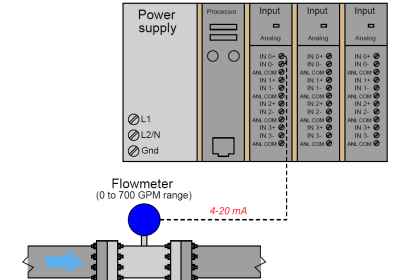
A transmitter is an electronic device that is generally mounted in the field in close proximity to a sensor. The sensor (also known as a transducer) measures a physical variable such as temperature or pressure and outputs a very low level electronic signal.
The basic function of the transmitter is to provide the correct electrical power to turn on (or excite) the sensor then to read the low level sensor signal, amplify it to a higher level electrical signal and send that signal a long distance to a control or read-out device.
Since low-level electrical signals do not transmit long distances with great accuracy, installing a transmitter generally gives a tremendous improvement in the accuracy of the information delivered to a larger control system. Typically the output form the transmitter is 4-20 mA or 0-10 V
14. Why 4-20 mA preferred over 0-10 V signal ?
The 0-10 V signal has tendency to drop because of line resistance. If the distance between sensor and input card is more the signal will not properly represent the field value.
The 4-20 mA will travel a long distance without dropping signal value.
15. Why 4-20 mA preferred over 0-20 mA signal ?
With 0- 20 mA you can not distinguish between minimum field value and connection break. With 4-20 mA, internal circuit can distinguish between connection break of minimum value.
Normally when the value is minimum the transmitter will give you 4 mA while in case of connection breakage it will give 0 mA.
16. Difference between 2 wire, 3 wire and 4 wire transmitter.
In 2 wire transmitter the power and signal are transmitted through same cable.
In 3 wire transmitter the data signal and power are with respect to common ground.
In 4 wire transmitter two wires for power supply and two for signals. Only current transmitters can be used as 2 wire transmitters.
17. What is a “Smart” Transmitter ?
A “Smart” transmitter is a transmitter that uses a microprocessor as the heart of the electronics.
In addition, a “Smart” transmitter will output some type of remote digital communications allowing you to read and set-up the device from a remote position.
18. What is Field bus ?
Fieldbus is a general term for a digital only, high speed communications protocol. The key attribute to Fieldbus communications is higher speed communications with the possibility of addressing multiple transmitters all on the same field wiring.
The Foundation Fieldbus is a specific digital protocol that is often shortened to just be called Fieldbus. Other digital only communications such as Profibus are also Fieldbus protocols
19. What is Actuator ?
In a closed-loop control system, the part of the final control element that translates the control signal into action by the control device.
An actuator is a component of a machine that is responsible for moving or controlling a mechanism or system.
An actuator requires a control signal and a source of energy. The control signal is relatively low energy and may be electric voltage or current, pneumatic or hydraulic pressure, or even human power.
20. Explain Working of RTDs
Resistance Temperature Device works on the principles that the resistance of the material changes as its temperature changes.
Temperature is determined by measuring resistance and then using the RTD Resistance vs Temp characteristic to detect temperature.
Typical elements used for RTD are Nickel, Copper and Platinum. Platinum is widely used in RTDs because of accuracy.
PT 100 means at 0 deg temp 100 ohms resistance. A typical RTD consists of a fine platinum wire wrapped around a mandrel and covered with a protective coating (glass or ceramic).
21. Temperature measurement range supported by RTDs?
The RTD work on temperature range between–250 to 850 deg C.
22. Explain Working of Thermocouple
Thermocouple consists of two strips or wires made up of different metals and joined at one end. The temperature at that juncture induces an electromotive force (emf) between the other ends.
As the temperature goes up the emf also increases. Through standard charts and tables the corresponding temperature can be found out.
The relationship between the thermocouple output and the temperature is quite non linear.
Different metallurgies produce different outputs. The different metallurgies and different lineararities result in different thermocouple designations such as “J”, “K,”, “N”, “L”, etc.
23. What is Cold Junction compensation?
The industry accepted standard for the temperature at open end is 0 deg C.
Therefore most tables and chart make the assumption that the temp at open end is 0 deg C. In industry the open ends are always at actual room temperature and not 0 deg C.
The emf adjustment because of difference between the actual temp and 0 deg C is referred as Cold Junction Correction (CJ Correction)
24. Temperature measurement range supported by thermocouple ?
The thermocouple work on broad temperature range ie –270 to 2300.
25. Can we split one T/C signal to two separate instruments?
No. The T/C signal is a very low-level millivolt signal, and should only be connected to one device.
Splitting to two devices may result in bad readings or loss of signal.
The solution is to use a “dual” T/C probe, or convert one T/C output to a 4-20 mA signal by using a transmitter or signal conditioner; then the new signal can be sent to more than one instrument
26. What are the flow measuring instruments used in Flow measurement ?
- Differential pressure meters
- Positive displacement
- Velocity meters
27. Explain working of differential pressure measurement ?
Suitable restriction placed in flow stream causes a differential pressure across it.
As flow depends upon differential pressure (Head) & area, so any of them or both can be varied for varying flow.
28. What are the components of differential flow sensor ?
For creating differential pressure : Orifice plate, Venturi Tube, Flow Nozzle , pitot tube
For measuring pressure : U-Tube Manometers, Ring–Balance Manometer, D.P. Cell
29. What type of pressure sensors used in pressure measurement?
30. Explain working of differential pressure transmitters.
Process pressure is transmitted through isolating diaphragms and oil fill fluid to a sensing diaphragm. The sensing diaphragm is a stretched spring element that deflects in response to differential pressure across it.
The displacement of the sensing diaphragm, a maximum deflection of0.004 inch (0.10 mm), is proportional to the applied pressure.
Capacitor plates on both sides of the sensing diaphragm detect the position of the diaphragm.
The transmitter electronics convert the differential capacitance between the sensing diaphragm and the capacitor plates into a two- wire, 4-20 mA dc signal and a digital output signal.
31. What is Control Valves ?
The control valve, commonly named the final control element of control contains a pneumatic device that converts the control signal from the controller in action, regulating the flow.
A control valve is a valve used to control fluid flow by varying the size of the flow passage as directed by a signal from a controller.
This enables the direct control of flow rate and the consequential control of process quantities such as pressure, temperature, and liquid level.
32. What type of control valves used in the industry ?
- ON – OFF SERVICES :- Gate, Ball, Diaphragm, Plug, Butterfly valves.
- THROTTLING SERVICES :- Globe, Butterfly, Diaphragm, Pinch valves.
- NON – REVERSE FLOW :- Check valves.
33. What are the specifications of the control valve ?
Following specifications are used for control valve
- Flow medium and operating temperature
- Flow rate kg/hr or Nm3/hr Max/Min/Normal
- Inlet and Outlet pressure : kg/cm2 Max/Min/Normal
- Max. allowable diff. Pressure : kg/cm2
- Density of medium : kg/m3
- Viscosity
- Cv : Valve Flow Coefficient
34. What are the components of control valve ?
- Actuator, Body, Trim, Diaphragm, Diaphragm plate, Actuator stem
- Actuator spring, Seat, Travel Indicator, Valve stem, Gaskets, Yoke, Hand wheel
35. What is flow coefficient ?
It is the flow of water (G=1, T= 6 to 34 deg. C) through the valve at full lift in U.S gallon per minute with a pressure drop across the valve of 1 psi.
If you liked this article, then please subscribe to our YouTube Channel for PLC and SCADA video tutorials.
You can also follow us on Facebook and Twitter to receive daily updates.
Read Next:


Really very very good knowledge shared, appreciate it ……
It’s much importanant n useful…
You done a great job ..
Thank you ??
Thanks very much …so interesting
Dear Sir,
I have few queries related to Vibration.Could u pls find below and acknowledge those:
1) Vibration probe was set at -10 V DC at Steam turbine, why -10 V & also negative DC voltage?
2) -10V is the gap voltage between Probe tip & rotating surface. Could u pls send any formula for vibration calculation?
3) If we remove the probe outside, how much vibration we will get?
4 how much vibration for below or above -10V DC, how to calculate?
Check this article. Negative Voltage for Vibration Probes ?
This is a good refresher