Basically they are designed to follow the physical law that, within the elastic limit, stress is proportional to strain (Hooke’s Law), that is deflection is proportional to the pressure applied.
Types of Bourdon Tube
There are 3 main types of elastic elements for pressure measurement, namely
- Bourdon Tubes,
- Bellows, and
- Diaphragm.
1. C-Type Bourdon Tube
This instrument is by far the most common device used to indicate gauge pressure throughout the oil gas industry.
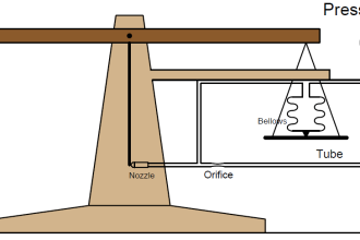
A bourdon tube obey Hookes Law, that is within elastic limits. Its free end will experience a movement that is proportional to the fluid pressure applied. The measuring element named for bourdon is partially flattened metal tube formed in a 250° Arc. The tube is sealed at one end (the tip ) and connected to the pressure at the other end (socket).
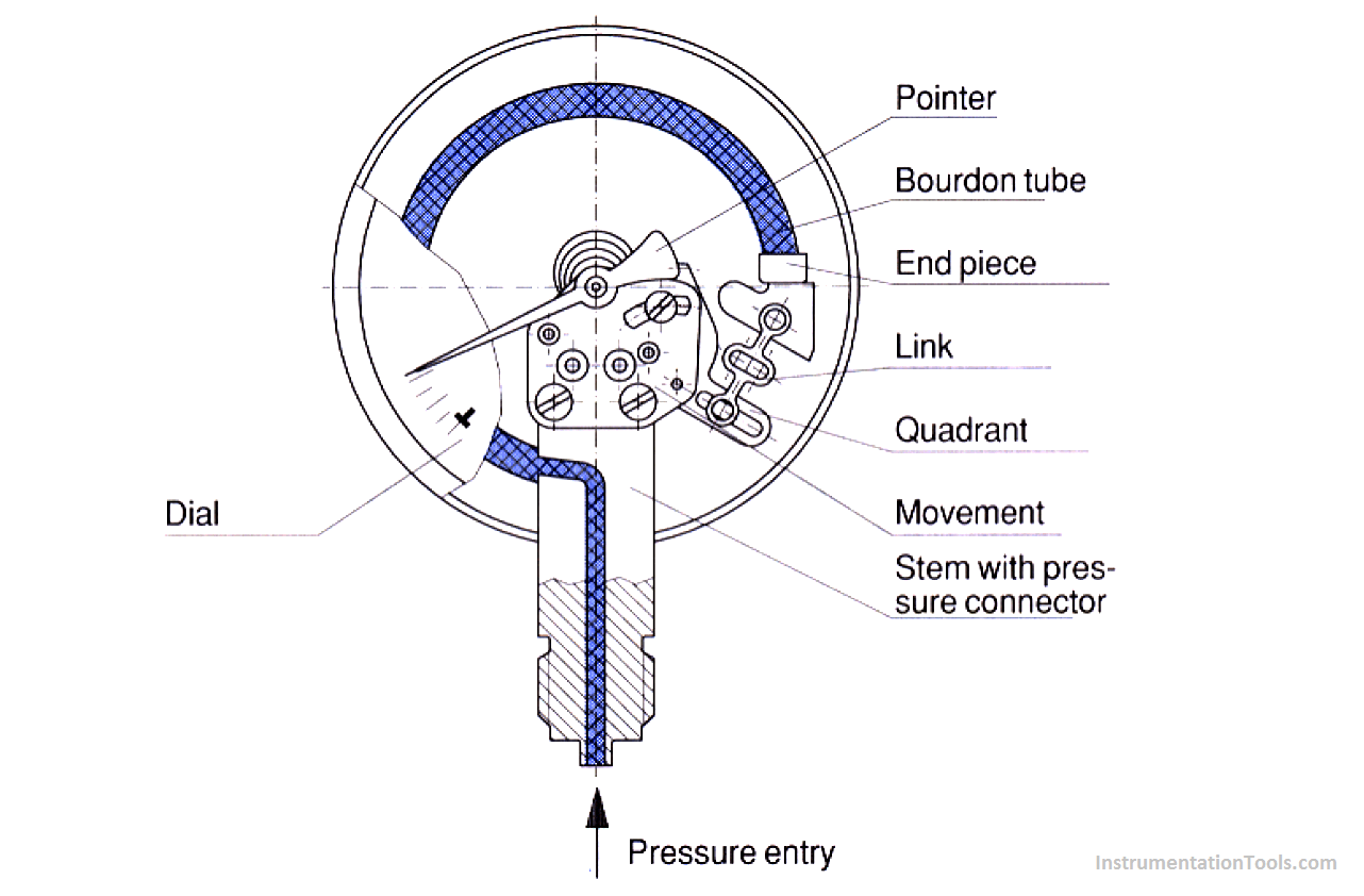
Any pressure inside the tube exceeding the pressure on the outside cause the tube to become more circular in cross section. As a result, the tip moves in an arc. This movement is connected through a level, quadrant and pinion to a pointer which moves round a scale to indicate the pressure.
The amount of movement of the free end of the tube is directly proportional to the pressure applied ( providing the tube elastic limit is not exceeded ).
Where greater sensitivity is required, the bourdon tube may be constructed in the form of a Spiral or Helix.
Also See : Bourdon Tube Pressure Gauge Animation
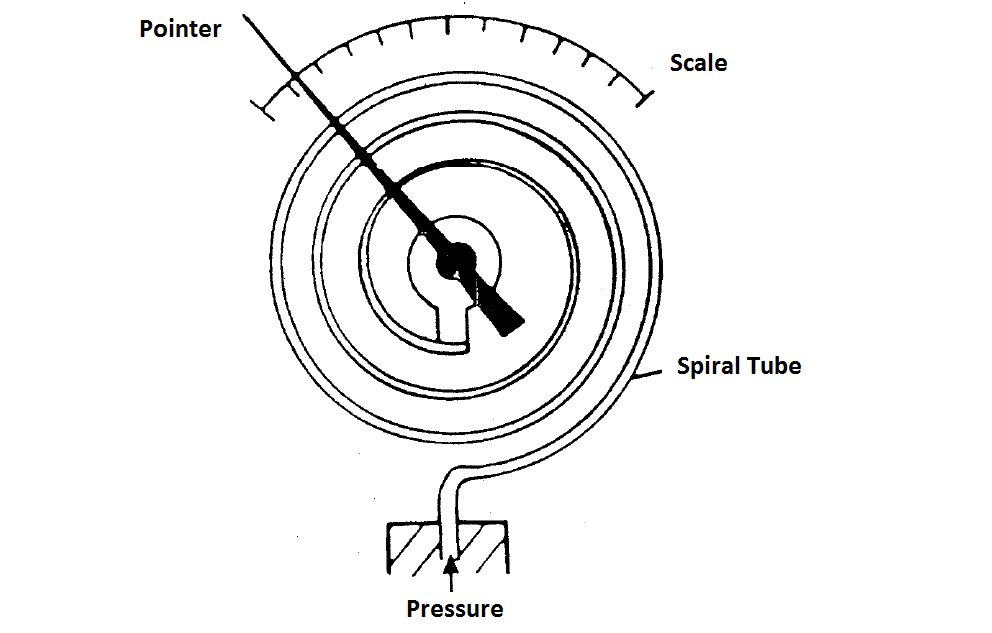
2. Spiral Bourdon Tube
Spiral Bourdon Tube is made by winding a partially flattened metal tube into a spiral having several turns instead of a single C-bend arc.
The tip movement of the spiral equals the sum of the tip movements of all its individual C-bend arcs.
Therefore it produces a greater tip movement with a C-bend bourdon tube. It is mainly used in low- pressure application. Spiral bourdon tube is shown in figure.
 3. Helical Bourdon Tube
Helical is a bourdon tube wound in the form of helix. It allows the tip movement to be converted to a circular motion.
By installing a central shaft inside the helix along its axis and connecting it to the tip, the tip movement become a circular motion of the shaft.

Advantages of the Spiral and Helical Tubes over the C-Type Bourdon Tube
1. Both the spiral and helical tubes are more sensitive than the C-Type tube. This means that for a given applied pressure a spiral or helical tube will show more movement than an equivalent C-Type tube, thus avoiding the need for a magnifying linkage.
2. Spiral and helical tubes can be manufactured in very much smaller sizes than the equivalent C-Type tubes. Hence, they can be fitted into smaller spaces, such as inside recorders or controller cases where a C-Type would be unsuitable because of the size.
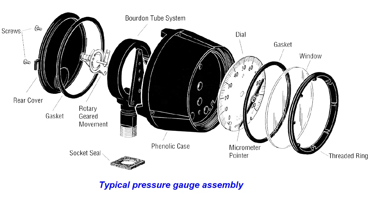
Pressure Gauge Assembly
APPLICATION OF BOURDON TUBE ELEMENTS
Before using a Bourdon tube on a particular process application, a number of questions need to be considered. We need only to consider two here.
1. What is the maximum operating pressure likely to be encountered by the tube? Manufacturers recommend that the normal operating pressure should not exceed 60% of the maximum scale reading. For example, if the normal working pressure were 6 bar, we would select a bourdon tube instrument ( pressure gauge) having full-scale deflection of 10 bar.
2. Is the process fluid corrosive or non corrosive? Material for the bourdon tubes must be able to handle the process fluid. Therefore, selection of pressure gauge must take into account the corrosivity of the line fluid.
Credits : N Asyiddin

Review Diagrams for clear vision. I love the work!