Inst ToolsInst ToolsInst Tools
  • Courses
  • Automation
    • PLC
    • Control System
    • Safety System
    • Communication
    • Fire & Gas System
  • Instrumentation
    • Design
    • Pressure
    • Temperature
    • Flow
    • Level
    • Vibration
    • Analyzer
    • Control Valve
    • Switch
    • Calibration
    • Erection & Commissioning
  • Interview
    • Instrumentation
    • Electrical
    • Electronics
    • Practical
  • Q&A
    • Instrumentation
    • Control System
    • Electrical
    • Electronics
    • Analog Electronics
    • Digital Electronics
    • Power Electronics
    • Microprocessor
  • Request
Search
  • Books
  • Software
  • Projects
  • Process
  • Tools
  • Basics
  • Formula
  • Power Plant
  • Root Cause Analysis
  • Electrical Basics
  • Animation
  • Standards
  • 4-20 mA Course
  • Siemens PLC Course
Reading: Fieldbus Flow Transmitter Configuration
Share
Font ResizerAa
Inst ToolsInst Tools
Font ResizerAa
  • Courses
  • Design
  • PLC
  • Interview
  • Control System
Search
  • Courses
  • Automation
    • PLC
    • Control System
    • Safety System
    • Communication
    • Fire & Gas System
  • Instrumentation
    • Design
    • Pressure
    • Temperature
    • Flow
    • Level
    • Vibration
    • Analyzer
    • Control Valve
    • Switch
    • Calibration
    • Erection & Commissioning
  • Interview
    • Instrumentation
    • Electrical
    • Electronics
    • Practical
  • Q&A
    • Instrumentation
    • Control System
    • Electrical
    • Electronics
    • Analog Electronics
    • Digital Electronics
    • Power Electronics
    • Microprocessor
  • Request
Follow US
All rights reserved. Reproduction in whole or in part without written permission is prohibited.
Inst Tools > Blog > Calibration > Fieldbus Flow Transmitter Configuration

Fieldbus Flow Transmitter Configuration

Last updated: February 19, 2019 4:42 pm
Editorial Staff
Calibration
No Comments
Share
1 Min Read
SHARE

Fieldbus Flow Transmitter Configuration

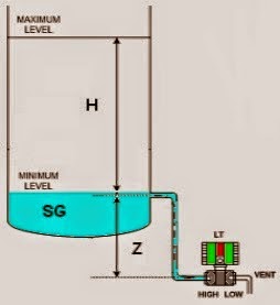
Suppose a FOUNDATION Fieldbus Flow transmitter (DP Type – Orifice) is connected to measure the flow of natural gas inside a pipeline.

The expected range of flow is 0 to 400 GPM and it generates an equal 0 to 135 inches water column pressure.

Determine the proper configuration parameters for this Fieldbus instrument’s Analog Input (AI) block:

Answer :

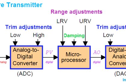
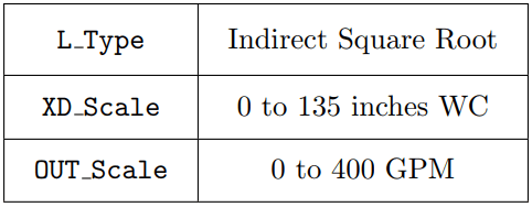
The Foundation Fieldbus Fow Transmitter have three important parameters to be configured.

The first parameter is “L_Type”, as it is orifice based DP type instrument, we have to select “Indirect Square Root” option.

The second parameter is “XD_Scale”, This scale is the pressure generates across orifice & which is 0 to 135 inches  WC.

The Third Parameter is “OUT_Scale”, This scale is the display range of actual units, which is 0 to 400 GPM.

Fieldbus Flow Transmitter Configuration

Foundation Fieldbus Pressure Transmitter

Also Read : Foundation Fieldbus Pressure Transmitter Configuration

Don't Miss Our Updates
Be the first to get exclusive content straight to your email.
We promise not to spam you. You can unsubscribe at any time.
Invalid email address
You've successfully subscribed !

Continue Reading

pH Analyzer Calibration and Troubleshooting
Calibration Procedure of Weighing Balance and Common Mistakes
Single Position Calibration of Temperature Bath
As-found and As-left Documentation during Calibration
DP type Flow Transmitter Preventive Maintenance and Calibration
DP Diaphragm Capillary Seal Level instrument Calibration Procedure
Share This Article
Facebook Whatsapp Whatsapp LinkedIn Copy Link
Share
Leave a Comment

Leave a Reply Cancel reply

Your email address will not be published. Required fields are marked *

Stay Connected

128.3kFollowersLike
69.1kFollowersFollow
210kSubscribersSubscribe
38kFollowersFollow

Categories

Explore More

Sample Raw DataSheet for Pressure Calibration
pH sensor calibration procedure
Closed tank DP Level Transmitter with wet leg Zero elevation Calibration
Installation and Calibration of Level Transmitter
What is Bump Testing ?
Hierarchy of Calibration Organizations
RTD Testing Methods in Calibration Laboratory
Types of Calibration

Keep Learning

Sand Probe Functional Testing

Sand Probe Functional Testing

Motor Operated Valve Functional Testing

Motor Operated Valve Functional Testing

Multiphase Flow Meter Calibration Procedure

Multiphase Flow Meter Calibration Procedure

Self Actuated Pressure Control Valve Functional Testing

Self Actuated Pressure Control Valve Functional Testing

Functional Testing of Control Valve Positioners

Functional Testing of Control Valve Positioners

Changing Process Medium Density has no influence on Level Indication (Full Absorption)

Nuclear Interface Level Measurement Principle, Limitations, Installation and Calibration

Differential Pressure Sensor Calibration

Differential Pressure Sensors Calibration Procedure

How to Test a Pressure Switch ?

How to Test a Pressure Switch ?

Learn More

Venturi Flow Measurement Principle

Why Flow is Directly Proportional to the Square Root of DP?

Add On Instructions Programming – Analog Input Devices in Studio 5000

Induction Motor Interview Questions Answers

Induction Motor Interview Questions Answers

Process Control Instrumentation Objective Questions

Process Control & Instrumentation Objective Questions – Set 3

Principle of Operation of PLC

Principle of Operation of PLC

Artificial intelligence in supply chain management

The Role of AI in Supply Chain Management – Examples & Benefits

Boolean Logic to PLC Programming

Boolean Logic to PLC Programming

Air Purge Level Measurement Principle

Air Purge or Air Bubbler Level Measurement

Menu

  • About
  • Privacy Policy
  • Copyright

Quick Links

  • Learn PLC
  • Helping Hand
  • Part Time Job

YouTube Subscribe

Follow US
All rights reserved. Reproduction in whole or in part without written permission is prohibited.
Welcome Back!

Sign in to your account

Username or Email Address
Password

Lost your password?