Inst ToolsInst ToolsInst Tools
  • Courses
  • Automation
    • PLC
    • Control System
    • Safety System
    • Communication
    • Fire & Gas System
  • Instrumentation
    • Design
    • Pressure
    • Temperature
    • Flow
    • Level
    • Vibration
    • Analyzer
    • Control Valve
    • Switch
    • Calibration
    • Erection & Commissioning
  • Interview
    • Instrumentation
    • Electrical
    • Electronics
    • Practical
  • Q&A
    • Instrumentation
    • Control System
    • Electrical
    • Electronics
    • Analog Electronics
    • Digital Electronics
    • Power Electronics
    • Microprocessor
  • Request
Search
  • Books
  • Software
  • Projects
  • Process
  • Tools
  • Basics
  • Formula
  • Power Plant
  • Root Cause Analysis
  • Electrical Basics
  • Animation
  • Standards
  • 4-20 mA Course
  • Siemens PLC Course
Reading: Capacitor
Share
Notification Show More
Font ResizerAa
Inst ToolsInst Tools
Font ResizerAa
  • Courses
  • Design
  • PLC
  • Interview
  • Control System
Search
  • Courses
  • Automation
    • PLC
    • Control System
    • Safety System
    • Communication
    • Fire & Gas System
  • Instrumentation
    • Design
    • Pressure
    • Temperature
    • Flow
    • Level
    • Vibration
    • Analyzer
    • Control Valve
    • Switch
    • Calibration
    • Erection & Commissioning
  • Interview
    • Instrumentation
    • Electrical
    • Electronics
    • Practical
  • Q&A
    • Instrumentation
    • Control System
    • Electrical
    • Electronics
    • Analog Electronics
    • Digital Electronics
    • Power Electronics
    • Microprocessor
  • Request
Follow US
All rights reserved. Reproduction in whole or in part without written permission is prohibited.
Inst Tools > Blog > Electrical Theory > Capacitor

Capacitor

Last updated: July 26, 2018 3:22 pm
Editorial Staff
Electrical Theory
No Comments
Share
2 Min Read
SHARE

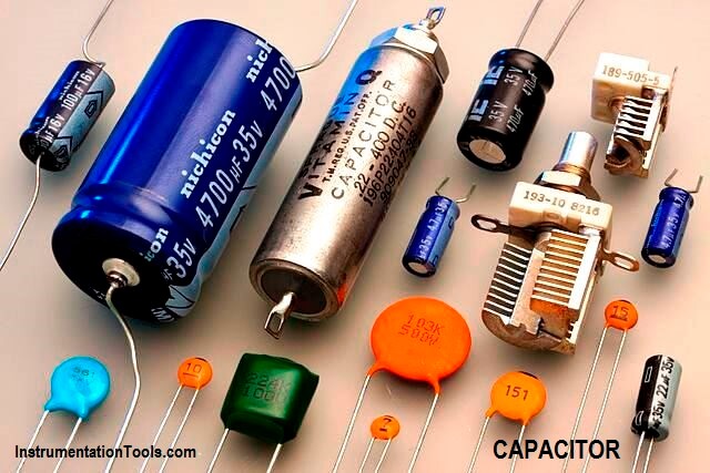
Electrical devices that are constructed of two metal plates separated by an insulating material, called a dielectric, are known as capacitors (Figure 10a). Schematic symbols shown in Figures 10b and 10c apply to all capacitors.

Capacitor and Symbols

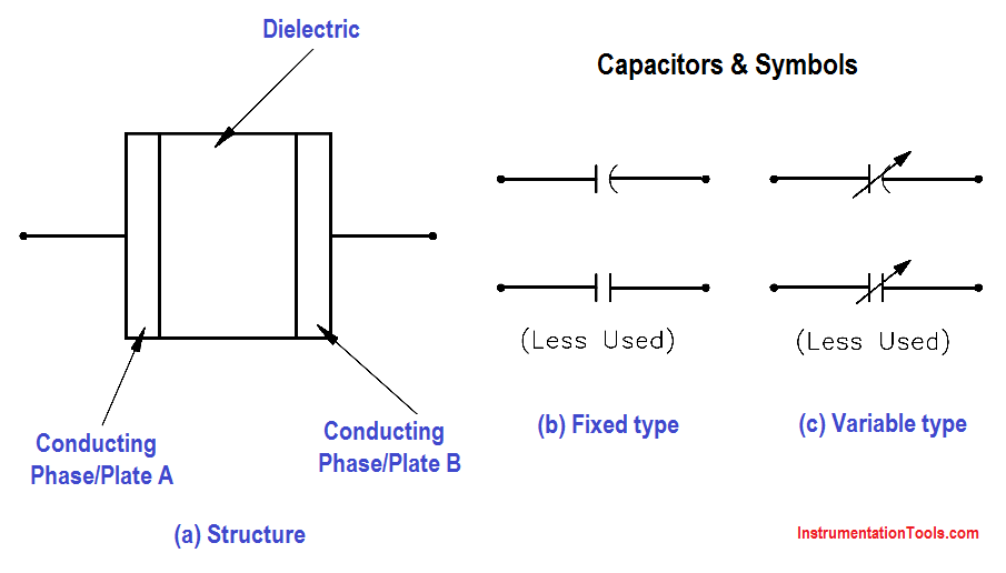
Figure 10 Capacitor and Symbols

The two conductor plates of the capacitor, shown in Figure 11a, are electrically neutral, because there are as many positive as negative charges on each plate. The capacitor, therefore, has no charge.

Capacitor Principle

Now, we connect a battery across the plates (Figure 11b). When the switch is closed (Figure 11c), the negative charges on Plate A are attracted to the positive side of the battery, while the positive charges on Plate B are attracted to the negative side of the battery. This movement of charges will continue until the difference in charge between Plate A and Plate B is equal to the voltage of the battery. This is now a “charged capacitor.” Capacitors store energy as an electric field between the two plates.

Charging a Capacitor

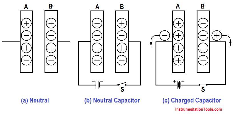
Figure 11 Charging a Capacitor

Because very few of the charges can cross between the plates, the capacitor will remain in the charged state even if the battery is removed. Because the charges on the opposing plates are attracted by one another, they will tend to oppose any changes in charge. In this manner, a capacitor will oppose any change in voltage felt across it.

If we place a conductor across the plates, electrons will find a path back to Plate A, and the charges will be neutralized again. This is now a “discharged” capacitor (Figure 12).

Discharging a Capacitor

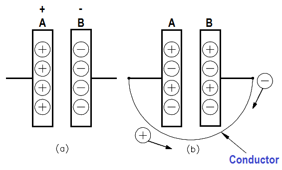
Figure 12 : Discharging a Capacitor

Don't Miss Our Updates
Be the first to get exclusive content straight to your email.
We promise not to spam you. You can unsubscribe at any time.
Invalid email address
You've successfully subscribed !

Continue Reading

AC Generator Theory
Impedance
Classification of Transformers
Ampere Hour Meter
DC Generator Internal Losses
Block Diagram
Share This Article
Facebook Whatsapp Whatsapp LinkedIn Copy Link
Share
Leave a Comment

Leave a Reply Cancel reply

Your email address will not be published. Required fields are marked *

Stay Connected

128.3kFollowersLike
69.1kFollowersFollow
210kSubscribersSubscribe
38kFollowersFollow

Categories

Explore More

Transformer Losses and Efficiency
Power in Balanced 3 Phase Loads
Moving Iron Vane Meter Movement
Single Phase Power Wiring Schemes
Resonance, Resonant Frequency, Series and Parallel Resonance
DC Generator Theory
AC Generation Analysis : Effective Values, Phase Angle and Frequency
Battery Operation : Series and Parallel

Keep Learning

Capacitors Connected in Parallel

Series and Parallel Capacitors

Parallel Circuit Unknown Resistance

Simplified Formulas for Parallel Circuit Resistance Calculations

D’Arsonval Movement

D’Arsonval Meter Movement

Ground Detector Lamp Method Principle

Ground Detector Principle

Inductor Principle

Inductor

DC Machine

DC Machines Construction

AC generator Voltage Regulators

AC Generator Voltage Regulators

Parallel Circuit Parallel Current Calculations

Parallel Circuit Current Calculations

Learn More

Power Systems Questions & Answers

Power Systems MCQ Series 14

Argonite/CO2 Flooding System Master & Slave Cylinder Operation

Differential Pressure Transmitters Static Pressure

What is Static Pressure Limit in DP Transmitter ?

Analyzers Questions and Answers

Pulse Height Analyzer Questions & Answers

Advantages & Disadvantages of Oil Circuit Breakers

Advantages & Disadvantages of Oil Circuit Breakers

Safety Instrumented System Interview Questions Answers

Safety Instrumented System Interview Questions and Answers

What is a Flange Gasket ?

What is a Flange Gasket ?

Standard Operating Procedure

What is SOP and How to Create an SOP?

Menu

  • About
  • Privacy Policy
  • Copyright

Quick Links

  • Learn PLC
  • Helping Hand
  • Part Time Job

YouTube Subscribe

Follow US
All rights reserved. Reproduction in whole or in part without written permission is prohibited.
Welcome Back!

Sign in to your account

Username or Email Address
Password

Lost your password?