In this article, you will learn the flow transmitters questions and answers related to flow measurement in industrial instrumentation.
Flow Transmitters Questions and Answers

What is CFM, SCFM, ACFM, Am³/hr, and N m³/hr?
- CFM is a unit of flow rate (cubic feet per minute)
- SCFM is a unit of flow rate (Standard Cubic Feet per Minute) at STP condition i.e. standard temperature 60º F and standard pressure 14.69 A PSI.
- ACFM (Actual Cubic Feet per Minute) is the actual flow at the operating temperature and pressure conditions.
- Am³/hr (Actual Cubic Meter per hour) is the actual flow at the operating temperature and pressure conditions.
- Nm³/hr (Normal Cubic Meter per hour) is normalized value of flow at NTP conditions i.e. flow at Normal Temperature 0º C and Normal Pressure 101.32 kPa condition.
Note : STP/NTP conditions are decided by different organizations/authorities as per their specifications.
Why back pressure is necessary?
When measuring liquids, back pressure in the flow line should be sufficient to prevent cavitation.
Cavitation occurs due to pressure drop at the obstruction in the flow line. Due to pressure drop, bubbles are formed and are driven to the further locations in the flow line where they break and erode the parts of flow line.
To avoid such cavitations, the back pressure in the line must be always greater than the vapor pressure of the fluid. To maintain back pressure in the line, larger pumping force is required.
In case of water and liquids of similar vapor pressure, required back pressure is approximately 1 kg/cm² at velocity of 6 meter/second.
When there is no back pressure in the pipeline, it can be created by placing a partially closed valve on the downstream side of the flow meter.
What is the Vortex Flow meter Principle?
Whenever an obstacle is placed in a flowing fluid, vortices are generated alternately on both sides of the obstacle.
The frequency of vortex generation is directly proportional to the velocity of the fluid and is independent of all other parameters.
Thus,
F α V
Frequency is directly proportional to velocity.
F = KV
Frequency gives inference of velocity.
Where
F = Frequency of Vortex Generation
V = Velocity of Fluid
K = Proportionality Constant
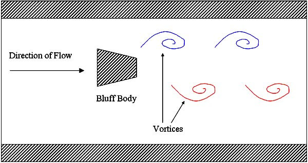
Fig : KARMAN VORTEX STREET IN PIPELINE
Flow Rate (M3/Hr) = Area of Pipe in M2 x Velocity of Fluid in M/sec x 3600 seconds
Why upstream and downstream straight length is required?
Flow Meter accuracy is guaranteed for a fully developed flow profile in the pipeline at the installed location.
Normally from flow disturbance point, flow is developed after a distance of about 20D or more.
Hence minimum upstream straight length should be 20D for normal pipelines.
Minimum downstream straight length should be 5D from the flow meter to avoid disturbances in the flow.
Can a differential pressure flowmeter handle turbulent flow?
Yes; though meters are unidirectional a straight run of tubing or pipe is not required.
What are the advantages of using a variable area flowmeter?
Inexpensive somewhat self-cleaning no power required available in different materials for chemical compatibility Low and constant pressure losses.
Suitable for very low flow rates Rangeability 10:1 Capable of measuring fluids of varying density and viscosity (compensation given by float design).
Must a rotameter be mounted vertically?
Generally, rotameters must be mounted vertically, because the float must center itself in the fluid stream.
At high flow rates, the float assumes a position towards the tip of the metering tube and at low flow rates positions itself lower in the tube.
Some of the rotameters have spring loaded floats and therefore may be mounted in any orientation.
Can we use a rotameter in a vacuum application or with back pressure?
Yes, but if you have a valve, it must be placed at the outlet (top of the flowmeter). This is done by inverting the tube inside the frame, and then turning over the frame.
At this position, the tube should read correctly from the original perspective and the valve should be at the outlet, or top of the flowmeter. This allows for proper control of the vacuum.
What is the difference between correlated and direct reading rotameters?
A direct reading flowmeter indicates the flow rate on its scale in specific engineering units (e.g. ml/min or scfh).
Direct reading scales are designed for a specific gas or liquid at a given temperature and pressure. While it is more convenient than a correlated flowmeter, a direct reading flowmeter is less accurate and limited in its applications.
A correlated flowmeter is scaled along either a 65mm or a 150mm length, from which a reading is taken.
The reading is then compared to a correlation table for a specific gas or liquid. This will give the actual flow in engineering units. One correlated flowmeter can be used with a variety of fluids or gases.
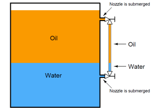
What are Multiphase Flow Meters?
Multiphase Flow Meters (MPFM) are devices used to measure the individual oil, water and gas flow rates in a multiphase flow.
The term MPFM is used to define also the metering of wet gas streams (i.e. multiphase flow where the gas content is very high).
A multiphase flow meter is a device used to measure the individual phase flow rates of constituent phases in a given flow (for example in oil and gas industry) where oil, water and gas mixtures are initially co-mingled together during the oil production processes.
Why is a Pressure Transmitter Installed Upstream of a Flow Transmitter?
- Upstream of a flow control valve a pressure transmitter is installed to measure the operating pressure.
- At times it is used for computing the true flow against the designed pressure.
- Downstream of the control valve the pressure changes as the control valve open and closes.
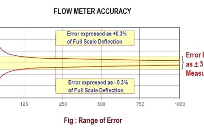
Differential Pressure Flow Meter Accuracy & Rangeability?
Performance of a head-type flowmeter installation is a function of the
- precision of the flow element and
- the accuracy of the d/p cell
On average, flow element precision is expressed in percentage of actual reading terms, whereas d/p cell accuracy is stated as a percentage of calibrated span.
A d/p cell typically provides accuracy of ±0.2% of the calibrated span. With no detrimental effect on accuracy, rangeability of a flowmeter can be extra enhanced by employing several d/p flowmeters in parallel runs.
How Hot Wire Anemometer Works?
The hot-wire anemometer, principally used in gas flow measurement, consists of an electrically
heated, fine platinum wire which is immersed into the flow.
As the fluid velocity increases, the rate of heat flow from the heated wire to the flow stream increases. Thus, a cooling effect on the wire electrode occurs, causing its electrical resistance to change.
In a constant-current anemometer, the fluid velocity is determined from a measurement of the resulting change in wire resistance.
In a constant-resistance anemometer, fluid velocity is determined from the current needed to maintain a constant wire temperature and, thus, the resistance constant
Explain Orifice Performance.
Principally, an orifice plate is a precision instrument. In best circumstances, the inaccuracy of Orifice plates can possibly fall in the range of 0.75-1.5% AR.
However, there are numerous error causing conditions which can terribly affect the accuracy of an Orifice plate.
Factors used to judge the performance of an Orifice plate:
- Precision in the bore calculations
- Quality of the installations
- Condition of the plate itself
- Orifice area ratio
- Physical properties of the fluid flow under measurement
A further class of installation depends upon following factors
- Tap location and circumstance. Generally, there are three ways to position a pressure tap.
- Provision of the process pipe
- Competence of straight pipe runs
- Gasket intervention
- Misalignment of pipe and orifice bores
- Lead line design
Extra detrimental conditions consist of
- Dulling of the sharp edge or nicks caused due to corrosion or erosion.
- Warpage of the plate because of waterhammer and dirt.
- Grease or secondary phase deposits on any of the orifice surface.
Any of the above said conditions has the tendency to affect the discharge coefficient of an orifice plate to a large extent.
Also Read : Flow Measurement Technologies
What is a Venturi Tube?
The venturi tube, illustrated in Figure, is the most accurate flow-sensing element when properly calibrated.
The venturi tube has a converging conical inlet, a cylindrical throat, and a diverging recovery cone.
It has no projections into the fluid, no sharp corners, and no sudden changes in contour.
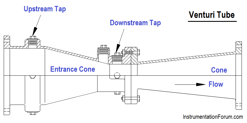
The inlet section decreases the area of the fluid stream, causing the velocity to increase and the pressure to decrease.
The low pressure is measured in the center of the cylindrical throat since the pressure will be at its lowest value, and neither the pressure nor the velocity is changing.
The recovery cone allows for the recovery of pressure such that total pressure loss is only 10% to 25%. The high pressure is measured upstream of the entrance cone.
The major disadvantages of this type of flow detection are the high initial costs for installation and difficulty in installation and inspection.
Explain Concentric, Segmental, and Eccentric Orifice Plates.
The concentric orifice plate is the most common of the three types. As shown, the orifice is equidistant (concentric) to the inside diameter of the pipe.
Flow through a sharp-edged orifice plate is characterized by a change in velocity. As the fluid passes through the orifice, the fluid converges, and the velocity of the fluid increases to a maximum value.
At this point, the pressure is at a minimum value. As the fluid diverges to fill the entire pipe area, the velocity decreases back to the original value. The pressure increases to about 60% to 80% of the original input value.
The pressure loss is irrecoverable; therefore, the output pressure will always be less than the input pressure. The pressures on both sides of the orifice are measured, resulting in a differential pressure that is proportional to the flow rate.
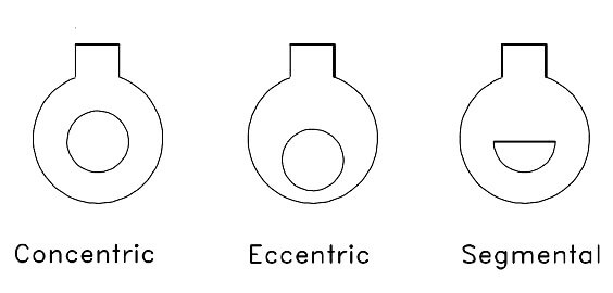
Segmental and eccentric orifice plates are functionally identical to the concentric orifice. The circular section of the segmental orifice is concentric with the pipe.
The segmental portion of the orifice eliminates damming of foreign materials on the upstream side of the orifice when mounted in a horizontal pipe.
Depending on the type of fluid, the segmental section is placed on either the top or bottom of the horizontal pipe to increase the accuracy of the measurement.
Eccentric orifice plates shift the edge of the orifice to the inside of the pipe wall.
This design also prevents upstream damming and is used in the same way as the segmental orifice plate.
Orifice plates have two distinct disadvantages; they cause a high permanent pressure drop (outlet pressure will be 60% to 80% of inlet pressure), and they are subject to erosion, which will eventually cause inaccuracies in the measured differential pressure.
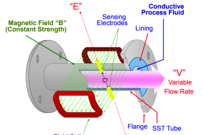
What are the selection criteria for Magnetic flowmeters?
The key questions which need to be answered before selecting a magnetic flowmeter are:
- Is the fluid conductive or water based?
- Is the fluid or slurry abrasive?
- Do you require an integral display or remote display?
- Do you require an analog output?
- What is the minimum and maximum flow rate for the flow meter?
- What is the minimum and maximum process pressure?
- What is the minimum and maximum process temperature?
- Is the fluid chemically compatible with the flow meter wetted parts?
- What is the size of the pipe?
- Is the pipe always full?
What are the Head types of flow meters?
In these head type flowmeters, some devices is inserted into a pipe carrying fluid.
It obstructs the flow of fluid and creates a pressure difference on either side of the device.
The most commonly used devices are as follows:
- Orifice plate.
- Venture plate.
- Flow nozzle.
- Doll flow tube.
- Pilot tube.
The basic principle of all such devices is that due to obstruction, the velocity of the fluid increases and the pressure decreases.
Then the volume flow rate is proportional to the square root of pressure difference across the obstruction. To measure pressure difference, diaphragm based differential pressure transducer is used.
What is a Pitot Tube or Total Pressure Probe?
A probe is a device used for point pressure measurement in a flowing fluid. This point measurement of pressure is done to determine fluid flow rate.
The most popular probe is the “PITOT TUBE” which is one of the total pressure probes. The Pitot tube measures the combined pressure (static pressure + impact pressure).
The pitot tube has one impact opening and eight static openings. The impact opening is provided to sense impact pressure and the static opening are provide to sense static pressure.
The pitot tube is introduced in the fluid flow area where point pressure details is required (which is an indirect measure of flow rate).
The pressure in the outer tube is the static pressure in the line. The total pressure in the inner tube is greater than static pressure. That is, total pressure is the static pressure plus the impact pressure.
The differential pressure (P1-P2) is measured using a differential pressure sensor. This differential pressure becomes a measure of flow rate at that point where the pitot tube is present in the flowing fluid.
What is a ‘k’ factor on a turbine meter?
Each turbine meter is specified with a ’k’ factor which represents the number of pulses produced per a known quantity of liquid.
Example: k = 265 pulsed/gallon
Generally, the ‘k’ factor is provided by the manufacturer.
What are the Types of Thermal mass flow meters?
Thermal mass flow meter types
- Constant Current Method
- Constant Temperature Method
What is a Flow profile or velocity profile?
The relative velocities of a fluid as it moves through a pipe, the velocity at the center being greater than the velocity at the pipe wall.
Laminar flow is characterized by large differences in velocity along the profile, while turbulent flow exhibits a “flatter” profile with more consistent velocity across the pipe diameter.
Relevant to insertion type flowmeters such as Pitot tubes where the flowing velocity is sampled at only one point in the flow stream.
How do you convert NM3/hr to MMSCFD?
Assume this is a gas. Different industries use different temperatures for “standard,” including but not limited to 15 °C, 60 °F, 20 °C, and 25 °C.
Unless you know which “standard” is meant, the final step is not possible.
Nm³ means the gas is measured at 0 °C and 1 atm (101.325 kPa).
Step (1): Multiply by 24 h/day to get Nm³/day.
Step (2): Multiply by 35.31467 ft³/m³ to get cubic feet/day at 0 °C and 1 atm.
Step (3): Determine “standard” temperature in °C, and multiply by temperature correction factor (273.15 + T)/273.15 to get SCFD.
Step (4) divide by 1 million to get MMSCFD.
What are the Types of Flow?
In general, we come across two types of flow in liquid flow Measurement operations.
Laminar flow:
This type of flow occurs at very low velocities or high viscosities.
In this, the liquid flows in smooth layers with the highest velocity at the center of the pipe and low velocities at the boundary (wall) of the pipe where the viscous forces hold it back.
Turbulent flow:
It takes place at high velocities or low viscosities.
In this, the liquid flow breaks up into turbulent eddies which flow through the pipe with the identical average velocity.
In this type of flow, fluid velocity is not much significant, and the velocity profile is a lot more uniform in shape.
What are the Factors Affecting Flow Rate?
From the basic relationship, we deduce that factors affecting liquid flow rate comprises average velocity of the flow and cross sectional area of the pipe.
Apart from these, other factors which can influence liquid flow rate are:
- Liquid’s viscosity
- Density
- Friction of the liquid in contact with the pipe
Also Read : Capillary Tubing Pressure Sensor Temperature & Elevation Problems
What are the Types of Ultrasonic Flowmeters?
Ultrasonic flowmeters are two types:
Doppler meters:
Doppler meters measure the frequency shifts caused by liquid flow. In this, two transducers are mounted in a case attached to one side of the pipe.
A signal of known frequency is transmitted into the liquid to be measured.
Solids, bubbles, or any other discontinuity in the liquid, cause the signal to be reflected to the receiver element.
Since the liquid causing the reflection is moving, the frequency of the returned pulse is shifted. This frequency shift is proportional to the liquid’s velocity or flow rate.
A portable Doppler meter which is competent enough of being operated on AC power or from a rechargeable power pack has lately been introduced.
A typical Doppler meter using sound pulse reflection principle.
Time-of-travel meters:
These are also known as Transit meters. They have transducers installed on each side of the pipe.
They use the transit time principle for flow measurement. In this, opposite sending and receiving transducers are employed to transmit signals through the flow.
The signal travels faster when moving with the flow stream rather than against the flow stream. The difference between the two transit times is used to determine the flow rate.
As per configuration, the sound waves travel between the devices at a 45 degree angle to the fluid flow direction.
The speed of the signal traveling between the transducers depends upon (increases or decreases) the direction of transmission and the velocity of the liquid being measured.
A time-differential relationship proportional to the flow can be acquired by transmitting the signal alternately in both directions.
A major limitation of time-of-travel meters is that the liquids being measured must be moderately free of entrained gas or solids. This is crucial for minimizing signal scattering and absorption.
What are the Types of Variable Area Flowmeters?
Variable area flowmeters are available in following variety of designs
- Rotameter (a float in a tapered tube)
- Orifice/Rotameter combination i.e. Bypass Rotameter
- Open-channel variable gate,
- Tapered plug, and
- Vane or Piston designs
What are the Advantages and disadvantages of Vortex-Shedding Flow Meters?
Advantages
- Accurate regardless of temperature, pressure, density and viscosity when flow is turbulent.
- Suitable for measuring liquids, gases and steam.
- Excellent for metering steam flow.
Disadvantages
- Flow must be turbulent.
- Ineffective for slurries and viscous flow.
How to convert SCFM to ACFM Conversion?
ACFM = SCFM x 14.696 / (Pa + 14.696) x degrees F / 530
Where as:
ACFM = Actual Cubic Feet per Minute measured gas flow
SCFM = Standard Cubic Feet per Minute gas flow
Pa = Operating Pressure in (PSIA) = PSIG + 14.696
Ta = Temperature in degrees Rankine = F + 460
Note: All calculations are at sea level.
What is Cryogenics and which Flow Meter Works with Cryogenic?
Cryogenics is the study of low temperatures.
The turbine flow meter is a very good choice of measurement due to the material and its ability to hold up to cryogenic temperatures and to accurately repeat at any flow rate.
The turbine creates minimal pressure drop or flow constriction in a catastrophic failure.
Flows can be maintained under any circumstance.
The turbine is also the most accurate and durable for use in a transport due to vibration resistance.
Why Generally a Flow Transmitter Installed Upstream of a Flow Control Valve?
A flow transmitter is always installed on the upstream of the flow control valve in order to maintain the operating pressure across the flow transmitter sensors.
Downstream of the control valve the pressure changes as the control valve open or closes.
What is the Purpose of Orifice Vent Hole?
Vent hole is a small hole which is provided in the upper region of orifice plate. Vent hole is required in liquid flow service where gas entrainment may occur.
Vent hole size could affect the accuracy of flow measurement. However, if the diameter of the vent hole is less than 10% of the orifice bore, then the unmeasured flow is less than 1% of the total flow.
Vent hole is not recommended in dirty fluid service or slurries as the hole could be plugged. In this application, the use of eccentric orifice plate becomes alternative.
What is the Purpose of Orifice Drain Hole?
Drain hole is a small hole which is provided in the lower region of orifice plate. Drain hole is required in gas flow service where liquid entrainment may occur.
Drain hole size could affect the accuracy of flow measurement. However, if the diameter of the drain hole is less than 10% of the orifice bore, then the unmeasured flow is less than 1% of the total flow.
Drain hole is not recommended in dirty fluid service or slurries as the hole could be plugged. In this application, the use of eccentric orifice plate becomes alternative.
Also Read : Flow Meter Installation Guidelines
Explain about Restrictive Flow Orifice.
A Restrictive Flow Orifice (RFO) is a type of orifice plate. They are used to limit the potential danger of an uncontrolled flow from, for example, a compressed gas cylinder by:
- limiting the accidental release of a hazardous gas (flammable, toxic, etc.) resulting from regulator or other component failure,
- restricting flow in a system in order to assure adequate pressure relief valve sizing and system over pressure protection, or
- restricting flow from bulk sources
What are the Types of Positive displacement meters?
The following are the Positive displacement flowmeters
- Reciprocating Piston type.
- Rotating or Oscillating Piston type.
- Nutating Disc type.
- Fluted Spiral Rotor type.
- Sliding vane type.
- Rotating vane type.
- Oval Gear type.
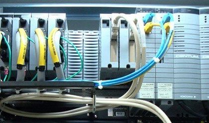
Which cable should be used to connect the Transmitter?
Generally three-core, twisted and shielded, 19/36 gauge cable.
In applications requiring mechanical ruggedness, we recommend three-core 1.5 mm² armored (shielded) cable.
Can we install flow meter in a vertical/inclined pipeline?
Yes, the flow meter can be installed in a vertical, inclined or in any angular position of pipeline for compressible fluids like low pressure air/gas, compressed air/gas.
For liquid applications in a vertical pipeline, the direction of flow should necessarily be from bottom to top, so as to avoid flow separation phenomenon.
Why is a ground strap required?
Ground strap is required for proper grounding (Earth) of meter body, i.e. both pipe and meter body should be at the same voltage potential.
Which gaskets are recommended?
For general applications asbestos grade or any non-yielding gaskets are required (Champion #20 or equivalent). NEVER use rubber gaskets!!!
Gasket I.D. must be 5mm larger than the meter I.D. Gaskets must be non-yielding so that they do not protrude and obstruct the flow.
Where should we place the taps for pressure gauges and temperature gauges?
Pressure gauge should be located within a distance of 4D to 7D on either upstream or downstream of the meter body.
Pressure tap fittings must not protrude in the pipe. Tap holes must be burr free.
RTD Temperature tap must be placed on the downstream side of the flow meter and within a distance of 5D to 10D from the flow meter body (since a temperature measuring probe /thermo-well can interfere with vortex generation)
Is the Flow Meter multi-variable?
No, the flow meter measures only the actual flow at operating pressure and temperature conditions i.e. AM³/HR or ACFM.
How do we pack the flow meter to send for servicing if required?
The Flow Meter system should be packed using adequate (2″-3″ thick) thermocol on all 6 sides inside a plywood box to avoid any transit damages.
Flow Meter and Flow Indicator should be packed in separate boxes.
“Used Goods / Goods for Repairs” Declaration should be accompanied with the consignment.
Reference: inconel flow meters
If you liked this article, then please subscribe to our YouTube Channel for Instrumentation, Electrical, PLC, and SCADA video tutorials.
You can also follow us on Facebook and Twitter to receive daily updates.
Read Next:
- Fixed Area Flow Meters
- Flow Measurement MCQ
- Interferometer Principle
- Calibration of Flow Meter
- Thermal flow meter Principle


Excellent article. Can you send me a link to access this information .
Excellent article. Thank you for the useful information.
Very good article thank you for the info.
Very nice info ,thanks