When a dangerous condition in a volatile process is sensed by process transmitters (or process switches), triggering a shutdown response from the logic solver, the final control elements must move with decisive and swift action.
Such positive response may be obtained from a standard regulatory control valve (such as a globe-type throttling valve), but for more critical applications a rotary ball or plug valve may be more suitable.
If the valve in question is used for safety shutdown purposes only and not regulation, it is often referred to as a chopper valve for its ability to “chop” (shut off quickly and securely) the process fluid flow. A more formal term for this is an Emergency Isolation Valve, or EIV.
Some process applications may tolerate the over-loading of both control and safety functions in a single valve, using the valve to regulate fluid flow during normal operation and fully stroke (either open or closed depending on the application) during a shutdown condition.
SIS Final Control Elements
A common method of achieving this dual functionality is to install a solenoid valve in-line with the actuating air pressure line, such that the valve’s normal pneumatic signal may be interrupted at any moment, immediately driving the valve to a fail-safe position at the command of a discrete “trip” signal.
Such a “trip” solenoid (sometimes referred to as a dump solenoid, because it “dumps” all air pressure stored in the actuating mechanism) is shown here, connected to a fail-closed (air-to-open) control valve:

Compressed air passes through the solenoid valve from the I/P transducer to the valve’s pneumatic diaphragm actuator when energized, the letter “E” and arrow showing this path in the diagram.
When de-energized, the solenoid valve blocks air pressure coming from the I/P and vents all air pressure from the valve’s actuating diaphragm as shown by the letter “D” and arrow. Venting all actuating air pressure from a fail-closed valve will cause the valve to fail closed, obviously.
If we wished to have the valve fail open on demand, we could use the exact same solenoid and instrument air plumbing, but swap the fail-closed control valve for a fail-open control valve.
When energized (regular operation), the solenoid would pass variable air pressure from the I/P transducer to the valve actuator so it could serve its regulating purpose.
When de-energized, the solenoid would force the valve to the fully-open position by “dumping” all air pressure from the actuator.
For applications where it is safer to lock the control valve in its last position than to have it fail either fully closed or fully open, we might elect to use a solenoid valve in a different manner:

Here, de-energization of the solenoid valve causes the I/P transducer’s air pressure output to vent, while trapping and holding all air pressure inside the actuator at the trip time.
Regardless of the valve’s “natural” fail-safe state, this system forces the valve to lock position (Note 1) until the solenoid is re-energized.
Note 1: This is assuming, of course, that there are no air leaks anywhere in the actuator, tubing, or solenoid which would cause the trapped pressure to decrease over time.
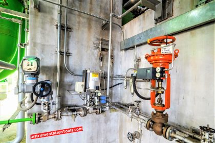
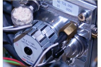
An example of a trip solenoid installed on a control valve appears in the following photograph.
This valve also happens to have a hand jack wheel installed in the actuating mechanism, allowing a human operator to manually override the valve position by forcing it closed (or open) when the hand wheel is turned sufficiently:

Of all the components of a Safety Instrumented System (SIS), the final control elements (valves) are generally the least reliable, contributing most towards the system’s probability of failure on demand (PFD).
Sensors generally come in at second place in their contribution toward unreliability, and logic solvers a distant third place. Redundancy may be applied to control elements by creating valve networks where the failure of a single valve does not cause the system as a whole to fail.
Unfortunately, this approach is extremely expensive, as valves have both high capital and high maintenance costs compared to SIS sensors and logic solvers.
A less expensive approach than redundancy to increasing safety valve reliability is to perform regular proof tests of their operation.
This is commonly referred to in the industry as partial stroke testing. Rather than proof-test each safety valve to its full travel, which would interrupt normal process operations, the valve is commanded to move only part of its full travel.
If the valve responds well to this “partial stroke” test, there is a high probability that it is able to move all the way, thus fulfilling the basic requirements of a proof test without actually shutting the process down (Note 2).
Note 2: Of course, if there is opportunity to fully stroke the safety valve to the point of process shutdown without undue interruption to production, this is the superior way of performing valve proof tests. Such “test-to-shutdown” proof testing may be scheduled at a time convenient to operations personnel, such as at the beginning of a planned process shutdown.