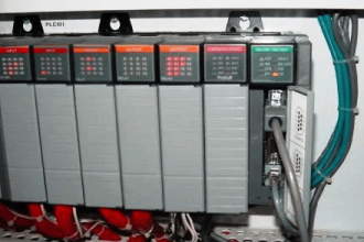
PLC consists of a processor unit and a collection of electronics I/O cards may be mounted locally or remotely. In a CPU unit where the software program is stored within. The below Figures show the wiring diagram connection from PLC to a solenoid valve.
The Power supply provides power to all modules in the PLC unit; however, it does not provide the DC voltages to the PLC’s peripheral I/O devices which requires high-rated currents and voltages.
Connect a Solenoid Valve with PLC
Output modules act as switches but rarely supply any power. The external power supply is connected to the output card and the card will switch the power on or off for each output channel.
Typical output voltages are listed below, and orders are placed as per their individual organizational requirement.
- 120 Vac
- 24 Vdc
- 12- to 48 Vac
- 12 to 48 Vdc
- 5 Vdc (TTL)
- 230 Vac
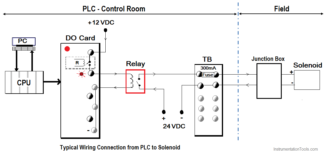
Wiring Connection from PLC to Solenoid
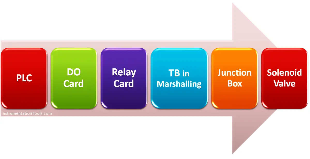
The solenoid valve is connected to the digital output module of the PLC. A branch cable (spur) is used to connect from the solenoid to the junction box in the field. The main cable (home run) is used to connect from the junction box to the marshalling cabinet in the control room. Then it is connected from the marshalling cabinet to the respective digital output (DO) card channel in the system cabinet.
Solenoid needs high-rating currents to operate. The PLC and its I/O modules uses low-rating currents only. So it’s not possible to directly use the PLC power supply which is used to power-up PLC cards.
To solve this problem, we have to use a separate power supply which is available in the marshalling cabinets. These are usually small positive and negative bus bar units that can supply +24 VDC with high-rated currents. Solenoid power will be used from this bus bar using intermediate relays. Relays are used such that solenoid receives power from these bus bar (+24 VDC) but relay controlled from the digital output cards.
Note: Solenoid can be operated with +12 VDC, +48 VDC, 110 VAC, 120 VAC, 230 VAC, etc. The wiring connections and power supply units will be changed accordingly.
When PLC gives the command to the Digital Output (DO) card. The DO card energizes the relay. The relay will be energized. The +24 VDC high-rated current also looped in the NO contact of this relay. When relay energized, this high-rated power will go to the field via junction box. The solenoid will be energized.
When PLC removes the command, then the DO card de-energizes this relay. The relay then removes the high-rated power to the solenoid, so solenoid will be de-energized.
These DO cards generally have 8 to 16 outputs of the same type with different and can be with different current ratings.
Relays, transistors, or triacs are a common choice when purchasing output cards.
Relays are the most adaptable output devices that are capable of switching both AC and DC outputs. But, they are slower in switching time. Relay outputs are often called dry contacts.
Transistors are limited to DC outputs, and
Triacs are limited to AC outputs. Transistors and Triac outputs are called switched outputs.
Dry Contacts
A dedicated relay is assigned to each digital output. This allows both AC and DC mixed voltages, as well as isolated outputs to protect other outputs and the PLC.
Response times are often greater than 10ms. This method is the least sensitive to voltage fluctuations and spikes.
Switched Outputs
A voltage is supplied to the PLC digital output card, and the card switches it to different outputs using solid-state circuitry with transistors or triacs. Triacs are well suitable for AC devices requiring less than 1A.
Transistor outputs use NPN or PNP transistors up to 1A generally. Their response time is well under 1ms.
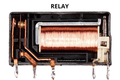
Relays
Even through relays are rarely used for control logic, they are still essential for switching large power loads. Some important terminology for relays is given below.
Contactors – are special relays for switching large current loads.
Also Read: PLC Wiring Types
Precautions to take while working with DO Relay
While selecting a relay, or relay outputs on a PLC, the most important consideration is the rated current, and voltage is taken into consideration.
- If the rated voltage is exceeded, the contacts will get wear out prematurely.
- If the rated voltage is too high fire is possible.
- The rated current is the maximum current that should be used for the relay. When this is exceeded the device will become too hot, and it will lead to early failure. The rated current values are generally given for both AC and DC, although DC ratings are below AC.
- If the actual loads used are below the rated load values the relays should work well indefinitely.
- If the rated values are exceeded a small amount the life of the relay will be shortened accordingly.
- Exceeding the rated values significantly may result in immediate failure and permanent damage.
- Rated Voltage – The recommended operation voltage for the coil. Lower levels can result in failure to operate, voltages above shorten its life.
- Rated Current – The maximum current before its contact damage occurs (welding or melting).
If you liked this article, then please subscribe to our YouTube Channel for PLC and SCADA video tutorials.
You can also follow us on Facebook and Twitter to receive daily updates.
Read Next:
- Earthing of PLC System
- Interposing Relay in PLC
- Different Parts of DCS
- Instrumentation Design
- PLC Alarm Acknowledge


A very good informative article on ” How to connect a solenoid with PLC”. At the same time, something is confusing in the connection drawing. It is that negative 12V, and a negative 24 connection is mentioned as GND. It can not connect with GND but a negative voltage terminal. Please clear my doubt.
Very good to keep updating