The most common failure mode for thermocouples is to fail open, otherwise known as “burning out.”
An open thermocouple is problematic for any voltage-measuring instrument with high input impedance because the lack of a complete circuit on the input makes it possible for electrical noise from surrounding sources (power lines, electric motors, variable-frequency motor drives) to be detected by the instrument and falsely interpreted as a wildly varying temperature.
For this reason it is prudent to design into the thermocouple instrument some provision for generating a consistent state in the absence of a complete circuit. This is called the burnout mode of a thermocouple instrument.
A simple thermocouple circuit equipped with burnout detection is shown in this diagram:
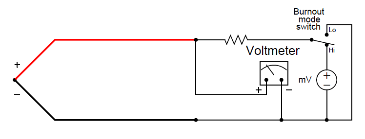
The resistor in this circuit provides a path for current in the event of an open thermocouple. It is sized in the mega-ohm range to minimize its effect during normal operation when the thermocouple circuit is complete. Only when the thermocouple fails open will the miniscule current through the resistor have any substantial effect on the voltmeter’s indication.
The SPDT switch provides a selectable burnout mode: in the event of a burnt-out thermocouple, we can configure the meter to either read high temperature (sourced by the instrument’s internal milli-voltage source) or low temperature (grounded), depending on what failure mode we deem safest for the application.


I don’t think the diagram makes sense. When assuming burnout ‘high’, the internal mV which is required for indication of ‘high’ will have voltage drop at the resistor and there will be no indication at the voltmeter. If my understanding is incorrect, please advise me.