Ultrasonic flow meter measure fluid velocity by passing high-frequency sound waves along the fluid flow path.
Fluid motion influences the propagation of these sound waves, which may then be measured to infer fluid velocity.
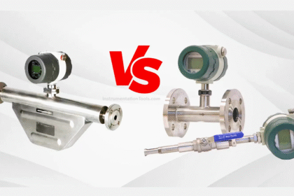
Ultrasonic Flow Meter
Two major sub-types of ultrasonic flow meters exist: Doppler and transit-time. Both types of ultrasonic flowmeter work by transmitting a high-frequency sound wave into the fluid stream (the incident pulse) and analyzing the received pulse.
Doppler flowmeters exploit the Doppler effect, which is the shifting of frequency resulting from waves emitted by or reflected by a moving object.
A common realization of the Doppler effect is the perceived shift in frequency of a horn’s report from a moving vehicle: as the vehicle approaches the listener, the pitch of the horn seems higher than normal; when the vehicle passes the listener and begins to move away, the horn’s pitch appears to suddenly “shift down” to a lower frequency.
In reality, the horn’s frequency never changes, but the velocity of the approaching vehicle relative to the stationary listener acts to “compress” the sonic vibrations in the air. When the vehicle moves away, the sound waves are “stretched” from the perspective of the listener.
The same effect takes place if a sound wave is aimed at a moving object, and the echo’s frequency is compared to the transmitted (incident) frequency. If the reflected wave returns from a bubble advancing toward the ultrasonic transducer, the reflected frequency will be greater than the incident frequency.
If the flow reverses direction and the reflected wave returns from a bubble traveling away from the transducer, the reflected frequency will be less than the incident frequency.
This matches the phenomenon of a vehicle’s horn pitch seemingly increasing as the vehicle approaches a listener and seemingly decreasing as the vehicle moves away from a listener.
A Doppler flowmeter bounces sound waves off of bubbles or particulate material in the flow stream, measuring the frequency shift and inferring fluid velocity from the magnitude of that shift.
What is a Doppler Flow Meter?

The requirement for there to be objects in the flow stream large enough to reflect sound waves limits Doppler ultrasonic flow meters to liquid applications.
“Dirty” liquids such as slurries and wastewater, or liquids carrying a substantial number of gas bubbles (e.g. carbonated beverages) are good candidate fluids for this technology.
It is unrealistic to expect that any gas stream will be carrying liquid droplets or solid matter large enough to reflect strong echoes, and so Doppler flow meters cannot be used to measure gas flow.
The mathematical relationship between fluid velocity (v) and the Doppler frequency shift (Δf) is as follows, for fluid velocities much less than the speed of sound through that fluid (v << c):
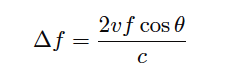
Where,
Δf = Doppler frequency shift
v = Velocity of fluid (actually, of the particle reflecting the sound wave)
f = Frequency of incident sound wave
θ = Angle between transducer and pipe centerlines
c = Speed of sound in the process fluid
Also See: Ultrasonic Flow meter Animation
Note how the Doppler effect yields a direct measurement of fluid velocity from each echo received by the transducer.
This stands in marked contrast to measurements of distance based on time-off light (time domain reflectometry – where the amount of time between the incident pulse and the returned echo is proportional to distance between the transducer and the reflecting surface)
such as in the application of ultrasonic liquid level measurement. In a Doppler flowmeter, the time delay between the incident and reflected pulses is irrelevant. Only the frequency shift between the incident and reflected signals matters.
This frequency shift is also directly proportional to the velocity of flow, making the Doppler ultrasonic flowmeter a linear measurement device.
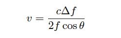
Re-arranging the Doppler frequency shift equation to solve for velocity (again, assuming v << c),
Knowing that volumetric flow rate is equal to the product of pipe area and the average velocity of the fluid (Q = Av), we may re-write the equation to directly solve for calculated flow rate (Q):
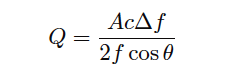
A very important consideration for Doppler ultrasonic flow measurement is that the calibration of the flow meter varies with the speed of sound through the fluid (c).
This is readily apparent by the presence of c in the above equation: as c increases, Δf must proportionately decrease for any fixed volumetric flow rate Q.
Since the flowmeter is designed to directly interpret flow rate in terms of Δf, an increase in c causing a decrease in Δf will thus register as a decrease in Q.
This means the speed of sound for a fluid must be precisely known in order for a Doppler ultrasonic flowmeter to accurately measure flow.
The speed of sound through any fluid is a function of that medium’s density and bulk modulus (how easily it compresses):
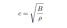
Where,
c = speed of sound in a material (meters per second)
B = Bulk modulus (pascals, or newtons per square meter)
ρ = Mass density of fluid (kilograms per cubic meter)
Temperature affects liquid density, and composition (the chemical constituency of the liquid) affects bulk modulus. Thus, temperature and composition both are influencing factors for Doppler ultrasonic flowmeter calibration.
Pressure is not a concern here, since pressure only affects the density of gases, and we already know Doppler flowmeters only function with liquids.
Following on the theme of requiring bubbles or particles of sufficient size, another limitation of Doppler ultrasonic flowmeters is their inability to measure flow rates of liquids that are too clean and too homogeneous. In such applications, the sound-wave reflections will be too weak to reliably measure.
Such is also the case when the solid particles have a speed of sound too close to the that of the liquid, since reflection happens only when a sound wave encounters a material with a markedly different speed of sound.
Doppler-type ultrasonic flowmeters are useless in applications where we cannot obtain strong sound-wave reflections.
Transit-time flowmeters, sometimes called counterpropagation flowmeters, are an alternative to Doppler ultrasonic flowmeters.
A transit-time ultrasonic flowmeter uses a pair of opposed sensors to measure the time difference between a sound pulse traveling with the fluid flow versus a sound pulse traveling against the fluid flow.
Since the motion of fluid tends to carry a sound wave along, the sound pulse transmitted downstream will make the journey faster than a sound pulse transmitted upstream:
What is a Transit-time Flow Meter?

The rate of volumetric flow through a transit-time flowmeter is a simple function of the upstream and downstream propagation times:
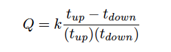
Where,
Q = Calculated volumetric flow rate
k = Constant of proportionality
tup = Time for sound pulse to travel from downstream location to upstream location (upstream, against the flow)
tdown = Time for sound pulse to travel from upstream location to downstream location (downstream, with the flow)
An interesting characteristic of transit-time velocity measurement is that the ratio of transit time difference over transit time product remains constant with changes in the speed of sound through the fluid.
If you would like to prove this to yourself, you may do so by substituting path length (L), fluid velocity (v), and sound velocity (c) for the times in the flow formula. Use tup = L/(c−v) and tdown = L/(c+v) as your substitutions, then algebraically reduce the flow formula until you find that all the c terms cancel. Your final result should be Q = 2kv/L .
When this equation is cast into terms of path length (L), fluid velocity (v), and sound velocity (c), the equation simplifies to Q = 2kv/L , proving that the transit-time flow meter is linear just like the Doppler flowmeter, with the advantage of being immune to changes in the fluid’s speed of sound.
Changes in bulk modulus resulting from changes in fluid composition, or changes in density resulting from compositional, temperature, or pressure variations therefore have little effect on a transit-time flow meter’s accuracy.
Not only are transit-time ultrasonic flow meters immune to changes in the speed of sound, but they are also able to measure that sonic velocity independent of the flow rate.
The equation for calculating speed of sound based on upstream and downstream propagation times is as follows:
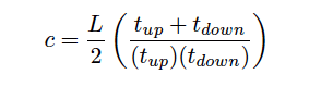
Where,
c = Calculated speed of sound in fluid
L = Path length
tup = Time for sound pulse to travel from downstream location to upstream location (upstream, against the flow)
tdown = Time for sound pulse to travel from upstream location to downstream location (downstream, with the flow)
While not necessary or even particularly relevant for the direct purpose of flow measurement, this inference of the fluid’s speed of sound is nevertheless useful as a diagnostic tool. If the true speed of sound for the fluid is known either by direct laboratory measurement of a sample or by chemical analysis of a sample, this speed may be compared against the flow meter’s reported speed of sound to check the flow meter’s absolute transit time measurement accuracy. Certain problems within the sensors or within the sensor electronics may be detected in this way.
A requirement for reliable operation of a transit-time ultrasonic flow meter is that the process fluid be free from gas bubbles or solid particles which might scatter or obstruct the sound waves.
Note that this is precisely the opposite requirement of Doppler ultrasonic flow meters, which require bubbles or particles to reflect sound waves.
These opposing requirements neatly distinguish applications suitable for transit-time flow meters from applications suitable for Doppler flow meters, and also raise the possibility of using transit-time ultrasonic flow meters on gas flow streams as well as on liquid flow streams.
Also Read: Ultrasonic Level Sensors Questions & Answers
One potential problem with any ultrasonic flow meter is being able to measure the true average fluid velocity when the flow profile changes with Reynolds number. If just one ultrasonic “beam” is used to probe the fluid velocity, the path this beam takes will likely see a different velocity profile as the flow rate changes (and the Reynolds number changes along with it).
Recall the difference in fluid velocity profiles between low Reynolds number flows (left) and high Reynolds number flows (right):

A popular way to mitigate this problem is to use multiple sensor pairs, sending acoustic signals along multiple paths through the fluid (i.e. a multipath ultrasonic flowmeter), and to average the resulting velocity measurements.
Dual-beam transit-time flow meters have been in use for well over a decade at the time of this writing (2009), and one manufacturer even has a five beam ultrasonic flowmeter model which they claim maintains an accuracy of ± 0.15% through the laminar-to-turbulent flow regime transition.
4 Channel Ultrasonic Flow Meter
A simplified illustration of a Daniel four-beam (or four “chord”) ultrasonic flowmeter is shown here:

Multipath ultrasonic flowmeters, by virtue of measuring more than one sound wave path through the fluid, also have the ability to detect irregular flow profiles.
Each sonic path between sensor pairs in a transit-time ultrasonic flow meter, called a chord, measures flow velocity. The velocities reported for each chord may be compared to the flow meter’s calculated average flow velocity, and expressed as velocity ratios.
A particular chord measuring a velocity greater than the flow meter’s average will report a velocity ratio greater than one (> 1), whereas a chord measuring a velocity less than the meter’s average will report a velocity ratio less than one (< 1).
In the Daniel four-chord ultrasonic flow meter, two chords (B and C) measure velocity near the center of the pipe while the others (A and D) measure velocity closer to the pipe walls.
In normal operation, the center chord velocity ratios should exceed the outer chord velocity ratios by a small amount, since the flow profiles of laminar and turbulent flow regimes alike exhibit a greater velocity at the center of a pipe than near the walls of a pipe.
Another parameter called profile factor expresses the chord velocity factors as a ratio, inner velocity factors over outer velocity factors: (B+C)/(A+D), a number which should always exceed one (> 1).
The exact value of this profile factor varies with the flow meter’s installation, and may shift over time if the flow profile shifts for some reason (e.g. partial blockage in a flow conditioner, piping change, accumulation of debris on pipe wall).
For example, a pipe accumulating dirt or other solid material on its walls over time will tend to slow down the velocity of fluid near the walls compared to the velocity of fluid in the center. This has the effect of decreasing chord A and D velocity ratios while increasing chord B and C velocity ratios, which in turn increases the profile factor value.
In this regard, the profile factor value for an operating flowmeter may be an important diagnostic tool, indicating some physical abnormality within the piping.
As previously mentioned, it is possible for a transit-time ultrasonic flowmeter to measure the speed of sound through the fluid from the sum of the upstream and downstream transit times.
Multipath transit-time flowmeters may use this feature to cross-check calculated speed of sound values measured by each chord, as a self-diagnostic tool.
Since each chord measures the same gas composition, each chord’s calculated speed of sound should be exactly equal. Significant differences in calculated speed of sound between chords suggests a failure in the acoustic sensor(s) or electronics for the errant chord.
Some modern ultrasonic flowmeters have the ability to switch back and forth between Doppler and transit-time (counterpropagation) modes, automatically adapting to the fluid being sensed. This capability enhances the suitability of ultrasonic flowmeters to a wider range of process applications.
Ultrasonic flowmeters are adversely affected by swirl and other large-scale fluid disturbances, and as such may require substantial lengths of straight pipe upstream and downstream of the measurement flowtube to stabilize the flow profile.
Like magnetic flowmeters, ultrasonic flowmeters are completely non-obstructive, which means they exhibit extremely low permanent pressure loss and will not accumulate debris.
Advances in ultrasonic flow measurement technology have reached a point where it is now feasible to consider ultrasonic flowmeters for custody transfer measurement of natural gas.
The American Gas Association has released a report specifying the use of multipath transit-time ultrasonic flowmeters in this capacity (Report #9). As with the AGA’s #3 (orifice plate) and #7 (turbine) high-accuracy gas flow measurement standards, the AGA9 standard requires the addition of pressure and temperature instruments on the gas line to measure gas pressure and temperature in order to calculate flow either in units of mass or in units of standardized volume (e.g. SCFM).
The measurement of temperature and pressure for a transit-time ultrasonic flowmeter has nothing to do with correcting errors within the meter itself, since we know transit-time flowmeters are inherently immune to changes in gas density or composition.
Temperature and pressure measurements are necessary for custody transfer applications simply because ultrasonic flowmeters, like turbine flowmeters, measure only volumetric flow.
The fair sale and purchase of a gas requires measurement of molecular quantity, not just volume, which is why a flow computer requires measurements of pressure and temperature in order to convert the ultrasonic flowmeter’s volumetric output to either mass flow or standardized volumetric flow.
A unique advantage of ultrasonic flow measurement is the ability to measure flow through the use of temporary clamp-on sensors rather than a specialized flow tube with built-in ultrasonic transducers. While clamp-on sensors are not without their share of problems, they constitute an excellent solution for certain flow measurement applications.
An important criterion for successful application of a clamp-on flow meter is that the pipe material be homogeneous in nature, to efficiently conduct sound waves between the process fluid and the clamp-on transducers. Porous pipe materials such as clay and concrete are therefore unsuitable for clamp-on ultrasonic flow measurement.
If you liked this article, then please subscribe to our YouTube Channel for Instrumentation, Electrical, PLC, and SCADA video tutorials.
You can also follow us on Facebook and Twitter to receive daily updates.
Read Next:
- Ultrasonic versus Radar Sensors
- Pneumatic P&ID Diagrams
- What is a Turbine flow meter?
- Ultrasonic Flow meters Factors
- Coriolis Flow Meter Uncertainty