Here we discuss about the general 4-20mA Loop Power Supply Questions and answers come across in industrial instrumentation.
4-20mA Loop Power Supply

What is a 4mA to 20mA signal?
The 4mA to 20mA signal is an industrial standard electrical signal that was designed to send information from one point to another. The 4/20mA signal can represent anything, and be scaled to any range of that quantity. What this means is that the 4/20mA signal can represent temperature, pressure, depth, humidity, or any number of things.
It also means that the 4/20mA signal can represent any range of values for that quantity, such as 0% to 100%, or 20% to 80%. Exactly what a 4/20mA signal represents is defined by the transmitter (sometimes referred to as a transducer) that is controlling the signal.
What components are needed for a 4mA to 20mA signal?
The components that are typically part of a 4/20mA installation are:
1) A power supply to provide the electricity for the loop
2) Wire (usually a “twisted pair”) to carry the electrical current
3) A transmitter to control the current through the circuit
4) A sensor wired to the transmitter to detect the quantity being measured
5) An indicator to show what the transmitter is measuring
6) A controller to act on the measured signal
Note: power supply, indicator, and controller are combined into one device. Sometimes the sensor and transmitter are combined into one device
Also Read : Types of 4-20mA Wiring
Sensors, transmitters, transducers: What?
Sensors are used to measure something, like temperature, pressure, weight, humidity, etc. The signal that a sensor makes is very small.
A transmitter consists of circuitry that amplifies this small signal and adjusts it to the 4/20mA output. When a sensor and a transmitter is designed and built as a single unit, it is frequently called a transducer.
How to wire a 4 to 20 mA system?
The sensor is always wired to the transmitter. The other components of the 4 to 20 mA system get wired in series, one after the other. Take a look at the various components, the transmitter, display, controller, and power supply. They all will be marked with a “+” power and a “-“ power terminal.
Connect the devices together so that the “+” power terminal of the power supply goes to the “+” terminal on the first device, the “-“ terminal of the first device to the “+” terminal of the second device, the “-“ terminal of the second device to the “+” terminal of the third device, and so on and so on until one wires back to the “-“ terminal of the power supply.
Because the wiring starts at the power supply and goes from one device to another, the 4/20mA system is commonly called a 4 to 20 mA loop.
What are the things need to know before design a 4/20mA loop?
The first task is to make sure that the power supply voltage is large enough to drive all the devices on the loop. The standard loop power supply is voltage for a Look on the data sheets for all the devices for an entry that identifies “power requirements”, “loop burden”, “drop”, or “impedance”.
We are looking for a value of voltage or resistance. Each device is going to require a certain amount of voltage from the loop to operate.
We will add these voltages together to make sure that they are less than the voltage available from the power supply. If the value is given as a resistance, we will use ohms law to convert it to a voltage.
Ohm’s law states that voltage equals current multiplied by resistance, so multiply the resistance by 0.02 and the resulting figure is the voltage we desire. Frequently a transmitter is labeled as “Power: X to Y Volts”. We will use the lower of the voltages in the calculation.
If the devices in the loop require more voltage to operate than the power supply delivers.
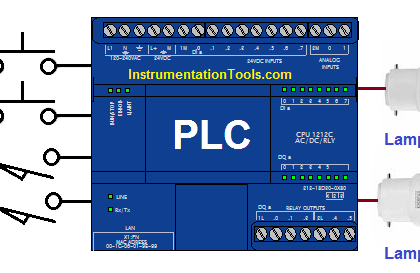
The second task is to identify all points in the loop that might be attached to earth ground. Devices like PLCs and power supplies frequently attach the connections to earth ground. Some sensors, like thermocouples, might not be electrically isolated and cause an unintended earth point.
Having more than one earth point in the loop will cause the loop to malfunction because current can flow between the earth points instead of through the wires.
The third task is to pick the cable. There are many existing solutions supplied by cable manufacturers. We recommend a twisted pair cable of at least #22 AWG.
The exact cable a particular installation will require will depend on the environment the cable is run through and the length of the cable. This document contains general advice and is not meant as a formal engineering solution to any particular application.
How do Get the display(s) on the 4 to 20 mA loop to read properly?
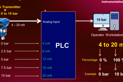
A 4 to 20 mA signal can represent anything, but the values that the loop represents are always defined by the transmitter (or transducer) in the loop. The range of the transmitter identifies the values being transmitted at 4mA and at 20mA.
Obtain the range of the transmitter and you will know what to set the display(s) to. Sometimes a transmitter sends a signal related to but not a direct measure of the desired quantity.
For instance, a pressure transducer is often used to measure the depth of a liquid, such as in wastewater facilities. It is common to use a 0/10psi pressure transducer, which would measure 0/23.1 feet of water. In cases like this it is necessary to apply math to achieve the proper results.
Sometimes scaling the display becomes confusing because what the transmitter is sending is very different from what is desired to display.
The best tool one can use to solve this problem is to draw a diagram of the installation, placing the sensor, labeling the desired measurement points, and the range that the sensor will measure. If necessary convert the sensor’s unit of measure into the display unit of measure (PSI to feet, for example) then add or subtract as necessary to get the scaling.
As an example, let’s say a 40PSI pressure transducer is mounted 75 feet down a well. The desire is to indicate the distance between the top of the well and water. 40 PSI * 2.311 feet/PSI = 92.4 feet.
The transducer is 75 feet down, so 4mA = -75 feet. Therefore, at 20mA the display should read -75 + 92.4 = 17.4 feet.
The loop is turned on but it isn’t doing anything, Why ?
A 4/20mA loop consists of many parts, and any one of the parts can be a problem. The first step is to check the wiring. Ensure that contact is made and to the correct terminals. The positive side of the loop devices should be wired toward the positive side of the power supply, the negative toward the negative.
A digital multimeter is an invaluable tool in troubleshooting a 4/20mA loop. Measure the voltage on the power supply to ensure that it powers up to the rated voltage.
Measure the voltage across the transmitter to ensure that the voltage is larger than the minimum requirement and that the polarity of the voltage is correct as labeled on the transmitter. A frequent cause of loop failure is due to the transmitter being wired up backwards.
Do you face any problems with loop power supply ? Share your experience with us.
If you liked this article, then please subscribe to our YouTube Channel for PLC and SCADA video tutorials.
You can also follow us on Facebook and Twitter to receive daily updates.
Read Next:
PLC Digital Signals Wiring Techniques
Solenoid Valve Functional Testing
Zener Diode Voltage Regulators


please, can you explain to me this example with more details …
As an example, let’s say a 40PSI pressure transducer is mounted 75 feet down a well. The desire is to indicate the distance between the top of the well and water. 40 PSI * 2.311 feet/PSI = 92.4 feet.
The transducer is 75 feet down, so 4mA = -75 feet. Therefore, at 20mA the display should read -75 + 92.4 = 17.4 feet.
thank you.