As we saw in the previous article, we may derive a relatively simple equation for predicting flow through a fluid-accelerating element given the pressure drop generated by that element and the density of the fluid flowing through it:
Volumetric Flow
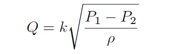
This equation is a simplified version of the one derived from the physical construction of a venturi tube:
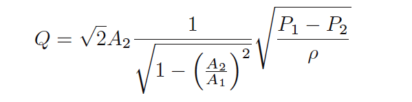
As you can see, the constant of proportionality (k) shown in the simpler equation is nothing more than a condensation of the first half of the longer equation: k represents the geometry of the venturi tube. If we define k by the mouth and throat areas (A1, A2) of any particular venturi tube, we must be very careful to express the pressures and densities in compatible units of measurement.
For example, with k strictly defined by flow element geometry (tube areas measured in square feet), the calculated flow rate (Q) must be in units of cubic feet per second, the pressure values P1 and P2 must be in units of pounds per square foot, and mass density must be in units of slugs per cubic foot.
We cannot arbitrarily choose different units of measurement for these variables, because the units must “agree” with one another. If we wish to use more convenient units of measurement such as inches of water column for pressure and specific gravity (unitless) for density, the original (longer) equation simply will not work.
However, if we happen to know the differential pressure produced by any particular flow element tube with any particular fluid density at a specified flow rate (real-life conditions), we may calculate a value for k in the short equation that makes all those measurements “agree” with one another.
In other words, we may use the constant of proportionality (k) as a unit-of-measurement correction factor as well as a definition of element geometry. This is a useful property of all proportionalities: simply insert values (expressed in any unit of measurement) determined by physical experiment and solve for the proportionality constant’s value to satisfy the expression as an equation
. If we do this, the value we arrive at for k will automatically compensate for whatever units of measurement we arbitrarily choose for pressure and density.
For example, if we know a particular orifice plate develops 45 inches of water column differential pressure at a flow rate of 180 gallons per minute of water (specific gravity = 1), we may insert these values into the equation and solve for k:
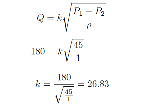
Now we possess a value for k (26.83) that yields a flow rate in units of “gallons per minute” given differential pressure in units of “inches of water column” and density expressed as a specific gravity for this particular orifice plate.
From the known fact of all accelerating flow elements’ behavior (flow rate proportional to the square root of pressure divided by density) and from a set of values experimentally determined for this particular orifice plate, we now have an equation useful for calculating flow rate given any set of pressure and density values we may happen to encounter with this particular orifice plate:
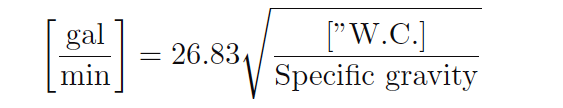
This k value lets us predict flow for any given pressure difference – and vice-versa – for this particular orifice plate.
Example Calculations
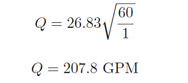
For example, if we wished to know the water flow rate corresponding to a pressure difference of 60 inches water column, we could use this equation to calculate a flow rate of 207.8 gallons per minute:
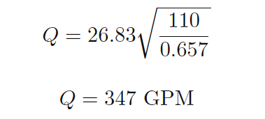
As another example, a measured differential pressure of 110 inches water column across this orifice plate generated by a flow of gasoline (specific gravity = 0.657) would correspond to a gasoline flow rate of 347 gallons per minute:
Suppose, though, we wished to have an equation for calculating the flow rate through this same orifice plate given pressure and density data in different units (say, kPa instead of inches water column, and kilograms per cubic meter instead of specific gravity).
In order to do this, we would need to re-calculate the constant of proportionality (k) to accommodate those new units of measurement. To do this, all we would need is a single set of experimental data for the orifice plate relating flow in GPM, pressure in kPa, and density in kg/m3.
Applying this to our original data where a water flow rate of 180 GPM resulted in a pressure drop of 45 inches water column, we could convert the pressure drop of 45 ”W.C. into 11.21 kPa and express the density as 1000 kg/m3 to solve for a new value of k:
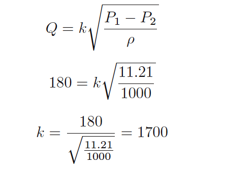
Nothing about the orifice plate’s geometry has changed from before, only the units of measurement we have chosen to work with.
Now we possess a value for k (1700) for the same orifice plate yielding a flow rate in units of “gallons per minute” given differential pressure in units of “kilopascals” and density in units of “kilograms per cubic meter.”
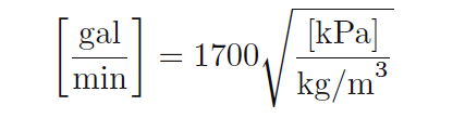
If we were to be given a pressure drop in kPa and a fluid density in kg/m3 for this orifice plate, we could calculate the corresponding flow rate (in GPM) with our new value of k (1700) just as easily as we could with the old value of k (26.83) given pressure in ”W.C. and specific gravity.
Credits: Tony R. Kuphaldt – Creative Commons Attribution 4.0 License
If you liked this article, then please subscribe to our YouTube Channel for Electrical, Electronics, Instrumentation, PLC, and SCADA video tutorials.
You can also follow us on Facebook and Twitter to receive daily updates.
Read Next:
- Capacitive Pressure Sensor
- How Orifice Measures Flow?
- Characteristics of Flow Meter
- What is a Weigh Feeder?
- Magnetic Flow Meter Earthing