Inst ToolsInst ToolsInst Tools
  • Courses
  • Automation
    • PLC
    • Control System
    • Safety System
    • Communication
    • Fire & Gas System
  • Instrumentation
    • Design
    • Pressure
    • Temperature
    • Flow
    • Level
    • Vibration
    • Analyzer
    • Control Valve
    • Switch
    • Calibration
    • Erection & Commissioning
  • Interview
    • Instrumentation
    • Electrical
    • Electronics
    • Practical
  • Q&A
    • Instrumentation
    • Control System
    • Electrical
    • Electronics
    • Analog Electronics
    • Digital Electronics
    • Power Electronics
    • Microprocessor
  • Request
Search
  • Books
  • Software
  • Projects
  • Process
  • Tools
  • Basics
  • Formula
  • Power Plant
  • Root Cause Analysis
  • Electrical Basics
  • Animation
  • Standards
  • 4-20 mA Course
  • Siemens PLC Course
Reading: What are the Orifice Plate Flow Requirements?
Share
Font ResizerAa
Inst ToolsInst Tools
Font ResizerAa
  • Courses
  • Design
  • PLC
  • Interview
  • Control System
Search
  • Courses
  • Automation
    • PLC
    • Control System
    • Safety System
    • Communication
    • Fire & Gas System
  • Instrumentation
    • Design
    • Pressure
    • Temperature
    • Flow
    • Level
    • Vibration
    • Analyzer
    • Control Valve
    • Switch
    • Calibration
    • Erection & Commissioning
  • Interview
    • Instrumentation
    • Electrical
    • Electronics
    • Practical
  • Q&A
    • Instrumentation
    • Control System
    • Electrical
    • Electronics
    • Analog Electronics
    • Digital Electronics
    • Power Electronics
    • Microprocessor
  • Request
Follow US
All rights reserved. Reproduction in whole or in part without written permission is prohibited.
Inst Tools > Blog > Flow Measurement > What are the Orifice Plate Flow Requirements?

What are the Orifice Plate Flow Requirements?

Orifice Plate Flow Requirements are to use straight run pipe length or a flow conditioner to reduce the straight run requirement.

Last updated: November 2, 2023 12:31 pm
Editorial Staff
Flow Measurement
No Comments
Share
2 Min Read
SHARE

The orifice flow meter is a well-established flow measurement method. The sizing, dimension, and installation requirements are dictated by ISO 5167-1 & ISO 5167-2.

Basically, the orifice sizing involves a coefficient that was determined from the empirical test. This coefficient is the coefficient of discharge.

During the test, the fluid flow is required to be a fully developed flow condition which means a fluid flow that is not a swirl-flow.
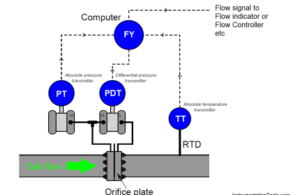
Orifice Plate

Orifice Plate Flow Requirements

This requirement is proved to be effective enough to produce the lowest uncertainty of coefficient of discharge which can lead to an accurate flow measurement reading.

If the fluid flow isn’t fully developed, it is proved also that the uncertainty of the coefficient of discharge is high which can lead to an inaccurate flow measurement reading.

The swirl flow itself can be caused by an elbow, control valve, or any other equipment in the upstream and downstream of the orifice plate.

There are two methods to establish the swirl-free conditions, by putting a certain straight run pipe length and by using an additional flow straightener or flow conditioner to reduce the straight run requirement.

ISO 5167-2 has already specified the requirement of this straight run with or without a flow conditioner. The straight run on that standard was determined experimentally and give a practical number that shall be followed to get the required flow meter uncertainty.

If you liked this article, then please subscribe to our YouTube Channel for Instrumentation, Electrical, PLC, and SCADA video tutorials.

You can also follow us on Facebook and Twitter to receive daily updates.

Read Next:

  • Integral Flow Orifice Assembly
  • What is an Orifice Flange?
  • Types of Orifice Tappings
  • What are the different Orifice Plates?
  • Turndown ratio of Orifice Plates
Don't Miss Our Updates
Be the first to get exclusive content straight to your email.
We promise not to spam you. You can unsubscribe at any time.
Invalid email address
You've successfully subscribed !

Continue Reading

Multiphase Flow Meter Calibration Procedure
Hot Wire Anemometer Principle and Types
Microwave Flow Sensor – Working Principle and Applications
DP type Flow Transmitter Preventive Maintenance and Calibration
Dall Tube Flow Meter – Principle, Advantages, Disadvantages
Working Principle of Vortex Flow Meter
Share This Article
Facebook Whatsapp Whatsapp LinkedIn Copy Link
Share
Leave a Comment

Leave a Reply Cancel reply

Your email address will not be published. Required fields are marked *

Stay Connected

128.3kFollowersLike
69.1kFollowersFollow
210kSubscribersSubscribe
38kFollowersFollow

Categories

Explore More

Principle of Flow Switch
Prover Tank Calibration and Mass Flow Meter Verification Procedure
Different Flow Measurement Technologies
What is a Square Root Extractor? – DP Flow Measurement
Difference between Invasive, Non-invasive, Intrusive & Non-intrusive
Configure the Instruments in Flow Control Loop
Flow Nozzle Principle, Advantages, Disadvantages, Applications
Importance of Flow Meter Turndown Ratio

Keep Learning

Laminar Flow Meter Working Principle

Laminar Flow Meter Working Principle

Averaging Pitot Tubes

Pitot Tube Problems and Troubleshooting Steps – Flow Instrument

multiphase-flowmeter-working-principle

What are Multiphase Flow Meters? – Working Principle, Advantages

Orifice Flow Meter With DP Transmitter

What is an Orifice Meter?

Vortex Flow Meter Principle

Vortex Flow meter Animation

Lobed Impeller Flow Meters Working Principle

Lobed Impeller Flow Meters Working Principle

Flow meter Turndown Ratio

Why Turndown Ratio is important when Selecting a Flow Meter?

Measuring Instruments

Flow Instruments – Selection, Principle & Application

Learn More

Digital Electronics Multiple Choice Questions

Programmable Read Only Memory Objective Questions – Part 2

Calibration of Weight

Calibration of Weight using the ABBA Method

PLC Lamp Control using Logic Condition

Lamp Control using PLC Logic Condition

Voltage Polarities

Voltage Polarity and Current Direction

Instrumentation Engineering Quiz

Instrumentation Engineering Quiz – Set 1

SCADA System

What is SCADA System?

Sheet Metal Fabrication Manufacturing and Design

Ideal Guide To Sheet Metal Fabrication Manufacturing and Design

Thermo Electric Transducers Objective Questions

Thermo Electric Transducers Objective Questions

Menu

  • About
  • Privacy Policy
  • Copyright

Quick Links

  • Learn PLC
  • Helping Hand
  • Part Time Job

YouTube Subscribe

Follow US
All rights reserved. Reproduction in whole or in part without written permission is prohibited.
Welcome Back!

Sign in to your account

Username or Email Address
Password

Lost your password?