When a fluid moves with high Reynolds number past a stationary object (a “bluff body”), there is a tendency for the fluid to form vortices on either side of the object. Each vortex will form, then detach from the object and continue to move with the flowing gas or liquid, one side at a time in alternating fashion.
This phenomenon is known as vortex shedding, and the pattern of moving vortices carried downstream of the stationary object is known as a vortex street.
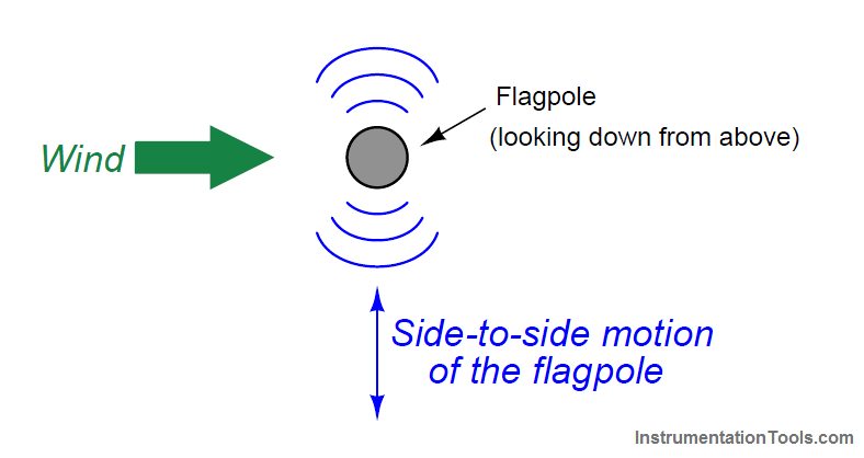
It is commonplace to see the effects of vortex shedding on a windy day by observing the motion of flagpoles, light poles, and tall smokestacks.
Each of these objects has a tendency to oscillate perpendicular to the direction of the wind, owing to the pressure variations caused by the vortices as they alternately form and break away from the object:
Vortex Shedding
This alternating series of vortices was studied by Vincenc Strouhal in the late nineteenth century and later by Theodore von K´arm´an in the early twentieth century.
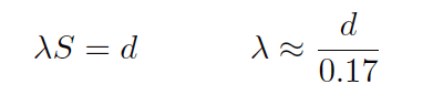
It was determined that the distance between successive vortices downstream of the stationary object is relatively constant, and directly proportional to the width of the object, for a wide range of Reynolds number values (Note). If we view these vortices as crests of a continuous wave, the distance between vortices may be represented by the symbol customarily reserved for wavelength: the Greek letter “lambda” (λ).
Note: It is important to note that the vortex-shedding phenomenon ceases altogether if the Reynolds number is too low.
Laminar flow produces no vortices, but rather stream-line flow around any object placed in its way.
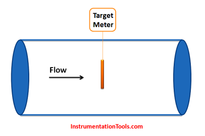
Vortex Flow Meter

The proportionality between object width (d) and vortex street wavelength (λ) is called the Strouhal number (S), approximately equal to 0.17:
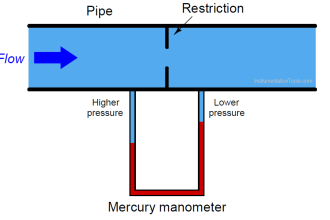
If a differential pressure sensor is installed immediately downstream of the stationary object in such an orientation that it detects the passing vortices as pressure variations, an alternating signal will be detected:

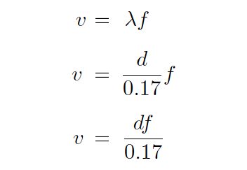
The frequency of this alternating pressure signal is directly proportional to fluid velocity past the object, since the wavelength is constant.
This follows the classic frequency-velocity-wavelength formula common to all traveling waves (λf = v).
Since we know the wavelength will be equal to the bluff body’s width divided by the Strouhal number (approximately 0.17), we may substitute this into the frequency-velocity-wavelength formula to solve for fluid velocity (v) in terms of signal frequency (f) and bluff body width (d).
Thus, a stationary object and pressure sensor installed in the middle of a pipe section constitute a form of flow meter called a vortex flow meter.
Like a turbine flow meter with an electronic “pickup” sensor to detect the passage of rotating turbine blades, the output frequency of a vortex flow meter is linearly proportional to volumetric flow rate.
The pressure sensors used in vortex flow meters are not standard differential pressure transmitters, since the vortex frequency is too high to be successfully detected by such bulky instruments.
Instead, the sensors are typically piezoelectric crystals. These pressure sensors need not be calibrated, since the amplitude of the pressure waves detected is irrelevant.
Only the frequency of the waves matter for measuring flow rate, and so nearly any pressure sensor with a fast enough response time will suffice.
Also See: Vortex Flow Meter Animation
Like turbine meters, the relationship between sensor frequency (f) and volumetric flow rate (Q) may be expressed as a proportionality, with the letter k used to represent the constant of proportionality for any particular flowmeter:
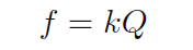
Where,
f = Frequency of output signal (Hz)
Q = Volumetric flow rate (e.g. gallons per second)
k = “K” factor of the vortex shedding flow tube (e.g. pulses per gallon)
Note : that if flow rate is to be expressed in units of gallons per minute as is customary, the equation must contain a factor for minutes-to-seconds conversion: f = kQ/60
This means vortex flow meters, like electronic turbine meters, each have a particular “k factor” relating the number of pulses generated per unit volume passed through the meter.
Counting the total number of pulses over a certain time span yields total fluid volume passed through the meter over that same time span, making the vortex flow meter readily adaptable for “totalizing” fluid volume just like turbine meters.
The direct proportion between vortex frequency and volumetric flow rate also means vortex flow meters are linear-responding instruments just like turbine flow meters.
Unlike orifice plates which exhibit a quadratic response, turbine and vortex flow meters alike enjoy a wider range (turndown) of flow measurement and do not require special signal characterization to function properly.
Note :This k factor is empirically determined for each flow meter by the manufacturer using water as the test fluid (a factory “wet-calibration”), to ensure optimum accuracy.
Since vortex flow meters have no moving parts, they do not suffer the problems of wear and lubrication facing turbine meters. There is no moving element to “coast” as in a turbine flow meter if fluid flow suddenly stops, which means vortex flow meters are better suited to measuring erratic flows.
A significant disadvantage of vortex meters is a behavior known as low flow cutoff, where the flow meter simply stops working below a certain flow rate.
The reason for this is laminar flow: at low flow rates (i.e. low Reynolds number values) the effects of fluid viscosity overwhelm fluid momentum, preventing vortices from forming.
This cessation of vortices causes the vortex flowmeter to register absolutely no flow at all even when there is still some (laminar) flow through the pipe.
At high flow rates (i.e. high Reynolds number values), fluid momentum is enough to overcome viscosity and produce vortices, and the vortex flow meter works just fine.
The phenomenon of low-flow cutoff for a vortex flow meter at first seems analogous to the minimum linear flow limitation of a turbine flow meter.
However, vortex flow meter low-flow cutoff is actually a far more severe problem. If the volumetric flow rate through a turbine flow meter falls below the minimum linear value, the turbine continues to spin, albeit slower than it should.
If the volumetric flow rate through a vortex flow meter falls below the low-flow cutoff value, however, the flow meter’s signal goes completely to zero, indicating no flow at all. This idiosyncrasy makes vortex flow meters entirely unsuitable in applications where the desired flow measurement range extends all the way down to zero.
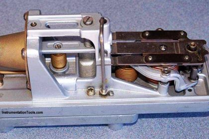
Vortex Flow Transmitter
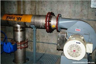
The following photograph shows a Rosemount vortex flow transmitter:

The next two photographs show close-up views of the flowtube assembly, front (left) and rear (right):

Vortex flow meters, like other velocity-based meters, are affected by large-scale turbulence in the fluid stream and therefore require some length of straight pipe both upstream and downstream of the flow meter to properly characterize the flow.
It is typical to install vortex flow meters with 10 pipe diameters of straight-length pipe upstream and 5 pipe diameters downstream.
If you liked this article, then please subscribe to our YouTube Channel for Instrumentation, Electrical, PLC, and SCADA video tutorials.
You can also follow us on Facebook and Twitter to receive daily updates.
Read Next:
- Flow Meters characteristics
- Orifice Flow Meter
- Variable Area Flow Meter
- Orifice Turndown ratio
- Flow Meter K-factor