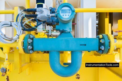
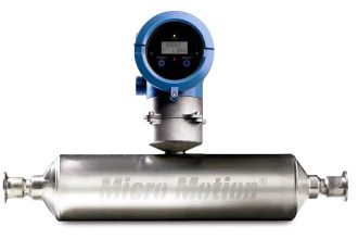
A turbine meter consists of a practically friction-free rotor pivoted along the axis of the meter tube and designed in such a way that the rate of rotation of the rotor is proportional to the rate of flow of fluid through the meter. This rotational speed is sensed by means of an electric pick-off coil fitted to the outside of the meter housing.
The only moving component in the meter is the rotor, and the only component subject to wear is the rotor bearing assembly. However, with careful choice of materials (e.g., tungsten carbide for bearings) the meter should be capable of operating for up to five years without failure.
Turbine Flow Meter
There are several characteristics of turbine flow meters that make them an excellent choice for some applications. The flow sensing element is very compact and lightweight compared to various other technologies. This can be advantageous in applications where space is a premium

Primary Vs. Secondary Standards
A primary standard calibration is one that is based on measurements of natural physical parameters (i.e., mass, distance, and time). This calibration procedure assures the best possible precision error, and through traceability, minimizes bias or systematic error.
A secondary standard calibration is not based on natural, physical measurements. It often involves calibrating the user’s flow meter against another flow meter, known as a “master meter,” that has been calibrated itself on a primary standard.
Calibration
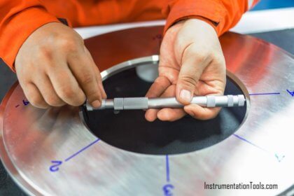
“To calibrate” means “to standardize (as a measuring instrument) by determining the deviation from a standard so as to determine the proper correction factors.” There are two key elements to this definition: determining the deviation from a standard, and ascertaining the proper correction factors.
Flow meters need periodic calibration. This can be done by using another calibrated meter as a reference or by using a known flow rate. Accuracy can vary over the range of the instrument and with temperature and specific weight changes in the fluid, which may all have to be taken into account.
Thus, the meter should be calibrated over temperature as well as range, so that the appropriate corrections can be made to the readings. A turbine meter should be calibrated at the same kinematic viscosity at which it will be operated in service. This is true for fluid states, liquid and gas.

Master Meter
A master meter is a flow meter that has been calibrated to a very high degree of accuracy. Types of flow meters used as master meters include turbine meters, positive displacement meters, venturi meters, and Coriolis meters.
The meter to be calibrated and the master meter are connected in series and are therefore subject to the same flow regime. To ensure consistent accurate calibration, the master meter itself must be subject to periodic re-calibration
Gravimetric Method
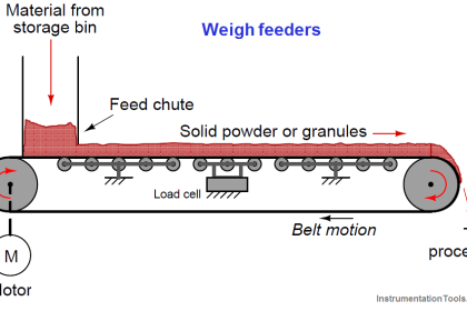
This is the weight method, where the flow of liquid through the meter being calibrated is diverted into a vessel that can be weighed either continuously or after a predetermined time.
The weight is usually measured with the help of load cells. The weight of the liquid is then compared with the registered reading of the flow meter being calibrated
Volumetric Method
In this technique, flow of liquid through the meter being calibrated is diverted into a tank of known volume.
The time to displace the known volume is recorded to get the volumetric flow rate eg:- gallons per minute. This flow rate can then be compared to the turbine flow meter readings
K-Factor
“K” is a letter used to denote the pulses per gallon factor of a flow meter.
Repeatability
The maximum deviation from the corresponding data points taken from repeated tests under identical conditions.
Flow Transfer Standards
Unlike primary flow standards, whose most important characteristics are their traceability to primary physical measurements (resulting in the minimization of absolute uncertainties, with less concern for usability or cost issues), the key criteria for secondary Flow Transfer Standards are portability, low cost and the ability to calibrate the flow meter in the physical piping configuration it lives in.
Instead of removing flowmeters from service for re-calibration, FTS devices allow users to “bring the calibrator to the flow meter.” These portable, documenting field flow calibrators are intended for in-line calibration and validation of meters using the actual process conditions for gas or liquid.
Advanced FTS systems in corporate hand-held electronics with built-in signal conditioners, thus eliminating bulky interface boxes and the need to carry a laptop computer into the field. High-quality Flow Transfer Standards also have the capability of measuring and correcting the influences of line pressure and temperature effects on flow.
Operation of a portable Flow Transfer Standard requires that a master meter be installed in series with the flow meter under test. The readings from these instruments are compared at various flow rates or flow totals.
A technician can install the master meter in the same system as the test meter, perform the calibration, and note any changes in performance. New calibration data might cause re-scaling or new data points to be programmed into a flow meter’s computer to align the measurement with the current flow calibration data.
Typical Calibration Techniques
Most flow meter calibration service suppliers provide a choice of calibration techniques to accommodate different applications and flow measurement requirements. One of the most common techniques is the single-viscosity calibration, which consists of running 10 evenly spaced calibration points at a specified liquid viscosity.
Single-viscosity calibrations are recommended when the viscosity of the liquid being measured is constant. If a higher degree of accuracy is needed, again, the more data points taken the better defined the meter calibration curve will be.

Strouhal Number/Roshko Number
The best, and only completely correct way to present the data for a Turbine Meter is the Strouhal Number as a function of the Roshko Number, i.e., through the use of two dimensionless parameters.
The St vs. Ro presentation takes into account all of the secondary effects to which the meter is sensitive. This presentation or correlation is correct for both liquids and gases. It is almost a must for gas calibrations since the density and kinematic viscosity are a function of both temperature and pressure
Your Calibrated Flowmeter
Once your flow meter is calibrated, it may still read exactly the same under the same flow conditions as it did before it was calibrated. The difference is that you will know exactly how close those values are to the true values, and you will have a formula to use to calculate the true values from the actual values read by your flow meter.
You can have a correction factor obtained from calibration which you can apply to the flow meter readings to obtain the correct or true flow meter readings. The k-factor ignores the effects of changing temperature on the meter body since the meter will change diameter when the temperature changes. The use of a Strouhal Number instead of a simple K-Factor will account for this temperature effect.
Source: engg-learning blog
If you liked this article, then please subscribe to our YouTube Channel for Instrumentation, Electrical, PLC, and SCADA video tutorials.
You can also follow us on Facebook and Twitter to receive daily updates.
Read Next:
- Flow Meter Verification
- Multiphase Flow Meter Calibration
- Instrument Technician Interview
- Questions on Flow Measurement
- Area Velocity Flow Meter


Dear sir,
I have problem to perform flowmeter calibration at site.
How to calibrate FLowmeter such as Dp flowmeter, vortex, turbine when construction phase or pre-commissioning phase at site?
hello, how I can calibrate the number of impulses in my satloc intelli flow meter, I do not know where to start.