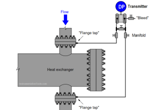
An impulse line is a physical process connection from a pipeline to an instrument in order to measure various process parameters such as pressure, differential pressure, level, flow, etc.
Impulse pipe must convey process pressure output accurately from the pipe tapping point to the transmitter.
Purpose of Impulse Line
An impulse pipe or line is a small bore pipe that is used to connect a point in a pipeline at which a process parameter is to be measured by an instrument.
For example, in a flow measurement using primary flow elements such as a Venturi meter, Pitot tube, Orifice meter, impulse lines are used to connect points upstream and downstream of the meter.
Impulse Pipe Material
Stainless Steel or high metal alloy selection depends upon process media, environmental conditions, protection against corrosion, process media pressure, and temperature.
Impulse Line Size
1/2 inch diameter impulse pipe is used for 4 to 8-inch process pipeline. 3/8 inch for 2 to 3-inch process pipeline.
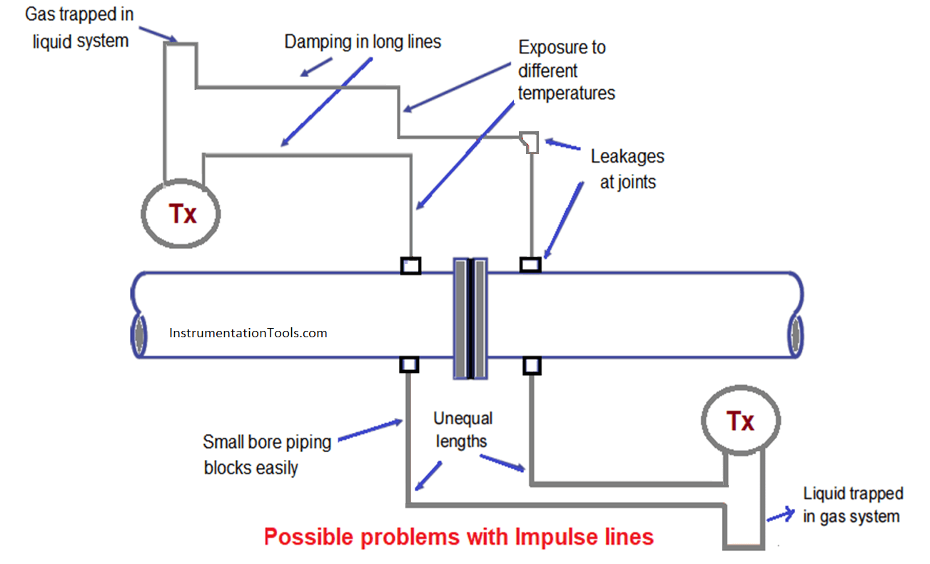
Possible Problems with Impulse Piping
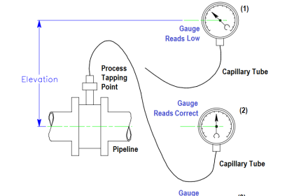
Proper care must be taken during the installation of impulse lines to avoid possible errors in measurement as shown in the figure below.
The transmitter readings will be affected due to the wrong installation of impulse lines when the transmitter is mounted at the top or bottom of the process line.
The Slope of an Impulse Line
Normally 80 mm/m is standard. For liquid services, level, etc., the slope should be down from the source point to the instrument, whereas for air and gas services it should be upward from the source point to the instrument.
If it is not possible to get such a slope, the maximum available slope is to be used.
The slope should never be less than 20 mm/m. Impulse lines connecting to the transmitter should be as short as possible to prevent errors.
Line drain/vent
High-point vent and low-point drain or a combination of vent and drain should be used to purge unwanted gas/liquid in the impulse lines.
Tapping Point Location
The preferred relative position of source point and instrument: Find below are the preferred locations with distinct advantages but are they are not mandatory.
Steam and Water Service
The instrument is preferred to mount below the tapping point to prevent entrapped gas bubbles. This will also help to reduce to a lower temperature at the instrument end.
Also, this arrangement avoids an additional need for a high-pressure vent.
Vacuum Service
The instrument is located above the source point so that the line is self-draining, preventing an error in measurement.
Air and Gas Services
\The instrument is located above the source point for the self-draining of condensed moisture.-
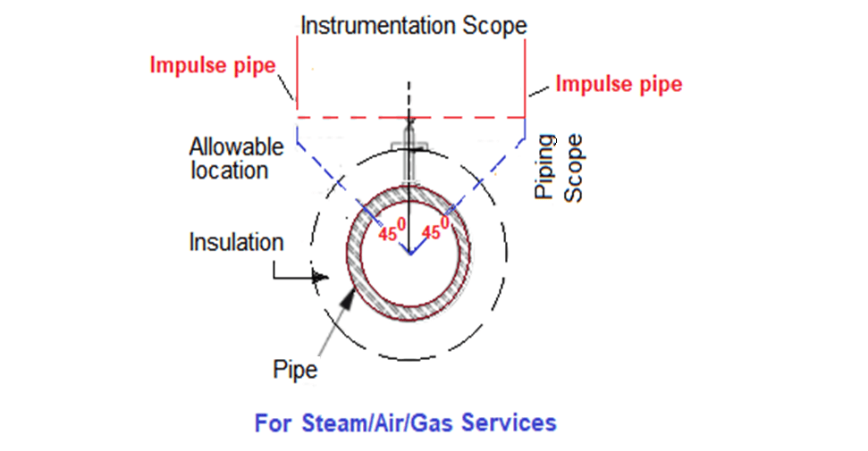
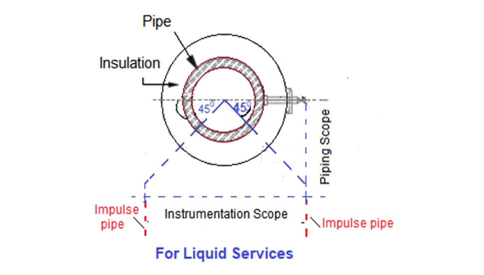
The Preferred Location of Tapping Point on the Pipe
Theoretically, tapping can be done at any position in a circular pipe cross-section in the plane, but there are certain preferences in locating the tapping points based on various services as detailed in the figure.
For Steam, Air, and Gas Services
The tapping point location preferable could be the top point, but it can be at any other position (upper half) with 45 degrees on both sides of the vertical line as shown in the figure below to avoid any liquid ingress.
For Liquid Service
The preferred tapping point locations are on either side of the horizontal line but can be at any other position (lower half) with 45 degrees on both sides of the horizontal line as shown in the figure below to avoid any entrapped gas.
But, it should not be at the bottom or in any position at the bottom beyond those discussed previously to avoid the ingress of pipe dirt particles in the impulse line.
Temperature Sensors (Elements)
These should be placed in flowing streams and not on stagnant fluid to get a representative reading, normally it should be directed to oppose the flow to create turbulence.
Purging Connections
In many cases purging connections are used to prevent plugging, freezing, and corroding of impulse lines. These purge fluids must be compatible (no interaction with process fluid) with the process fluid.
Care should be taken to see that purging does not initiate any error in the system. The quantity of gas/liquid purge is to be regulated.
Purge fluids are normally independent of process fluids so that it is available even when the process fluid is not operating. Normally a purging system has a check valve and also a shut-off valve.
If you liked this article, then please subscribe to our YouTube Channel for Instrumentation, Electrical, PLC, SCADA, and Industrial Automation video tutorials.
You can also follow us on Facebook and Twitter to receive daily updates.
If you liked this article, then please subscribe to our YouTube Channel for Instrumentation, Electrical, PLC, and SCADA video tutorials.
You can also follow us on Facebook and Twitter to receive daily updates.
Read Next:


The shield of Instrument cable. Shall we connect to earth both side or one side.
Ground all shielded cables at one end only. In case of long cables the ground potential may differ and generate circulating current flow through the shield which will make the signal noisy and even in correct.
what standards requiring that for liquid services the tapping point should be at 90 to 45deg.
Process Industry Practices
Process Control
PIP PCCGN002
General Instrument Installation Criteria
6.1.2 Instrument process connections shall be made to either the side, top, or upper
or lower 45-degree angle of process piping or equipment as directed by the
owner. When low-side connections are specified, these connections shall be
sufficiently high to prevent plugging by dirt or suspended solids.
Connections shall be short and without pockets.
Dear Rao sir,
kindly clarify why pressure transmitters Taping always for liquid service on top side. exam; water line
my query is In case of diaphragm seal even if the phase is gas/vapor, transmitter can be installed below level of tap point, what if the phase is liquid and the transmitter level is upper than tap point.