Restriction orifice (RO) is mainly used to achieve controlled or restricted flow of process medium.
Restriction Orifice
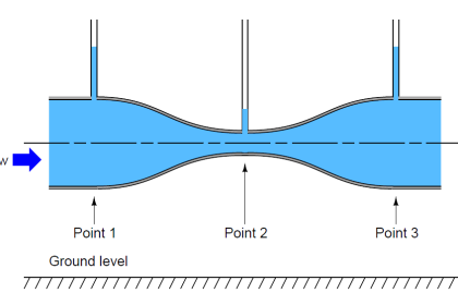
The orifice offers a restriction to the process flow and the pressure head drops from the upstream to the downstream.
The permanent pressure loss by the device is the intended pressure drop for which it is sized.
The area of the orifice determines the rate of flow at the outlet of a given process fluid for the specified pressure and temperature.
The responsibility for final restriction orifice sizing, selection & supply rests with the supplier.
Design and sizing of restriction orifice may require review by the specialist for stress and noise-related evaluation.
Types of Restriction Orifice Plates
Here is a description of a few common types of restriction orifice plate devices used in Oil and Gas applications.
- Single-stage Restriction Orifice,
- Single-stage Multi-hole Restriction Orifice,
- Multi-stage Restriction Orifice Plate Assembly,
- Conical-shaped Restriction Orifice Plate
Single-stage Restriction Orifice
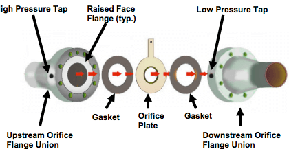
A single-stage restriction orifice is usually a plate or a block with a bore (orifice) sized to the intended permanent loss of pressure.
It is installed between the pipe flanges. Usually, it is not a thin orifice plate; it is a thick orifice plate.

Single-stage Multi-hole Restriction Orifice
A single-stage multi-hole restriction orifice plate is used to abate the noise generated by the device due to high velocity through the bore which offers restriction to the incoming fluid.
The flow at the inlet is now channeled into several streams through the multiple holes and this reduces the noise which would otherwise be above the acceptable limit if a single hole device is used.

Multi-stage Restriction Orifice Plate Assembly
These devices are used where the pressure reduction ratio is very high and cannot be achieved by a single-stage orifice plate. Thus a multistage device essentially consists of a number of single-stage devices built in a single spool.
Like a single-stage device, it can be of a single-hole multi-stage design, multi-hole multi-stage design, or a combination of both.

Conical-shaped Restriction Orifice Plate
Solve problems associated with orifice cavitation (Erosion, vibration, noise)

Eliminated damage caused by cavitation
- The energy dissipated inside the cone of the orifice, not at the pipe wall
- The conical orifice allows energy to dissipate before striking the pipe wall
Applications of Restriction Orifice Plates
Followings are a few examples of common applications where these restriction orifice devices are used to achieve controlled flow from the upstream to the downstream.
Restriction orifices are often exposed to severe flow conditions associated with large pressure reductions and the related fluid conditions caused by liquids flashing to a gas, cavitation, and sonic (choked) flow. Hence such conditions also are taken into consideration.
Restriction Orifice (RO) at the downstream of blowdown valves
These are used to ensure a controlled flow rate in a blowdown piping or blowdown header.
When the blowdown valve (which is usually an FB or RB ball valve) opens to release the high pressure on its upstream, the restriction orifice plate at its downstream ensures that the flow is not excessive to overload the flare header.
Usually, the pressure drop in the blowdown circuit across the restriction orifice could be very high say, typically 80-100 bar.
If the high-pressure drop is achieved through a single-stage device or by a device with not too many stages, there will be a fall in temperature during the blowdown event due to the Joule-Thompson effect. Thus the design of the RO needs to take care of the low temperature.
Restriction Orifice (RO) in pump re-circulation line
ROs are also used in centrifugal pump’s re-circulation line where a constant re-circulation flow is required and control of re-circulation and forward flow rate is not important.
The re-circulation ensures that cavitations/starvation cannot happen in the pump.
Restriction Orifice (RO) to restrict gas blow-by
A typical case is the flow of hydrocarbon condensate from the high-pressure separator to the low-pressure separator.
Usually, a level control valve (LCV) controls the level of the high-pressure separator. In case of valve failure, the valve needs to open fully to stop the separator from overflowing.
Full open of LCV is accompanied by the high rate of flow of condensate followed by the flow of gas. To stop the downstream relieving system from overloading the gas flow is controlled by a restriction orifice at downstream of the LCV.
A similar application is seen in the heating medium flow into the re-boiler to mitigate the effect of the heating medium valve fail open position.
Restriction Orifice (RO) to check excess flow
ROs are used to restrict the excessive flow in case of a rupture.
Thus in Well head applications if the down holes valves are to be closed due to fire, the hydraulic power oil to the valve actuator is depressurized by the use of a fusible plug which fuses and allows the hydraulic oil to leak through an RO at a restricted flow rate.
Restriction Orifice (RO) for controlled pressurization
During the start-up of a process plant, many plant sections are required to be pressurized with the incoming process fluid in a controlled manner.
This is because the upstream section will be usually at a much higher pressure than the downstream.
Thus if there is no restriction on the flow rate, the initial flow rate may be very high and may damage the pipeline and equipment.
ROs are used for gradual pressurization. To restrict the flow the ideal condition is to design for the choked flow for gas.
During the choked flow, the rate of flow will be less as it will be proportional to the square root of inlet pressure rather than to the differential pressure.
Codes and Standards
Though no internationally reputed codes and standards exist that directly address a restriction orifice but there are associated references and some are listed below:
(i) ISO 5167 Part 1: Measurement of fluid flow by means of pressure differential devices inserted in circular cross-section conduits running full – Part 1: General principles and requirements.
(ii) ISO 5167 Part 2: Measurement of fluid flow by means of pressure differential devices inserted in circular cross-section conduits running full – Part 2: Orifice plates.
(iii) IEC 60534-8-3: Industrial-process control valves – Part 8-3: Noise considerations –Control valve aerodynamic noise prediction method.
If you liked this article, then please subscribe to our YouTube Channel for Instrumentation, Electrical, PLC, and SCADA video tutorials.
You can also follow us on Facebook and Twitter to receive daily updates.
Read Next:
- Why was RTD installed after Orifice?
- Restriction Orifice after Blowdown valve
- Basics of Different Valve Types
- Orifice Drain and Vent Hole
- Flow Measurement Technologies


Hello Sir,
I am hareesh Instrument technician From Uae. I am a regular follower of Instrument tools.com,Today i wud like to ask to something about steam flow and its issues.Sir,we have a boiler and an FT in its output steam which is always going to negative flow exactly same as the actual flow on other boilers.I checked the orifice orientation its found ok.Observed dat low side is giving higher pressure always.Sir What can be the reason.How can i solve this issue.The Flow element tapping is flanged type.
1. Recheck installaton. Fow direction, Orifice plate upstream facing upstream, condensate pots are at the same elevation and transmitter calibration and if control system range is correct. DP transmitter can read from -URL to +URL. If it is smart transmitter check the calibration with HHT. It is quite difficult to understand how you get negative reading.