Perhaps the most common way in which the flow measurement accuracy of any flow meter becomes compromised is incorrect installation, and pressure-based flow meters are no exception to this rule.
Installation of Flow Meter
The following list shows some of the details one must consider in installing a pressure-based flow meter element:
- Necessary upstream and downstream straight-pipe lengths
- Beta ratio (ratio of orifice bore diameter to pipe diameter: β = d/D )
- Impulse tube tap locations
- Tap finish
- Transmitter location in relation to the pipe
Sharp turns in piping networks introduce large-scale turbulence into the flowstream.
Elbows, tees, valves, fans, and pumps are some of the most common causes of large-scale turbulence in piping systems.
Successive pipe elbows in different planes are some of the worst offenders in this regard.
When the natural flow path of a fluid is disturbed by such piping arrangements, the velocity profile of that fluid becomes distorted; e.g. the velocity gradient from one wall boundary of the pipe to the other will not be orderly.
Large eddies in the flow stream (called swirl ) will appear. This may cause problems for pressure-based flow elements which rely on linear acceleration (change in velocity in one dimension) to measure fluid flow rate.
If the flow profile is distorted enough, the acceleration detected at the element may be too great or too little, and therefore not properly represent the full fluid flow stream.
For this reason, pressure-based flow meters should always be located upstream of major disturbances such as control valves and pipe elbows where possible.

Even disturbances located downstream of the flow element may affect measurement accuracy if the disturbances are severe enough and/or close enough to the flow element.
Unfortunately, both upstream and downstream flow disturbances are unavoidable on all but the simplest fluid systems.
This means we must devise ways to stabilize a flow stream’s velocity profile near the flow element in order to achieve accurate measurements of flow rate.
A very simple and effective way to stabilize a flow profile is to provide adequate lengths of straight pipe ahead of (and behind) the flow element.
Given enough time, even the most chaotic flow stream will “settle down” to a symmetrical profile all on its own.
The following illustration shows the effect of a pipe elbow on a flow stream, and how the velocity profile returns to a normal (symmetrical) form after traveling through a sufficient length of straight pipe:

Recommendations for minimum upstream and downstream straight-pipe lengths vary significantly with the nature of the turbulent disturbance, piping geometry, and flow element.
As a general rule, elements having a smaller beta ratio (ratio of throat diameter d to pipe diameter D) are more tolerant of disturbances, with profiled flow devices (e.g. venturi tubes, flow tubes, V-cones) having the greatest tolerance (Note).
Ultimately, you should consult the flow element manufacturer’s documentation for a more detailed recommendation appropriate to any specific application.
In applications where sufficient straight-run pipe lengths are impractical, another option exists for “taming” turbulence generated by piping disturbances.
Devices called flow conditioners may be installed upstream of the flow element to help the flow profile achieve symmetry in a far shorter distance than simple straight pipe could do alone.
Flow conditioners take the form of a series of tubes or vanes installed inside the pipe, parallel to the direction of flow.

These tubes or vanes force the fluid molecules to travel in straighter paths, thus stabilizing the flowstream prior to entering a flow element:
Note : Flow elements with low beta ratio values tolerate greater disturbance in the flow pattern because they accelerate the flowstream to a greater degree.
This may be best visualized by a thought experiment where we imagine an orifice plate with a very large beta ratio (i.e. one where the bore size is nearly as large as the pipe diameter): such an orifice plate would hardly accelerate the fluid at all, which would mean a mis-shapen flow profile entering the bore would probably remain mis-shapen exiting it.
The acceleration imparted to a flowstream by a low-beta element tends to overshadow any asymmetries in the flow profile.
However, there are disadvantages to using low-beta elements, one of them being increased permanent pressure loss which may translate to increased operating costs due to energy loss.
Orifice Plate Installation
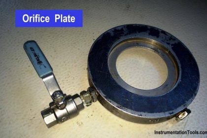
This next photograph shows a very poor orifice plate installation, where the straight-run pipe requirements were completely ignored:

Not only is the orifice plate placed much too close to an elbow, the elbow happens to be on the upstream side of the orifice plate, where disturbances have the greatest effect!
The saving grace of this installation is that it is not used for critical monitoring or control: it is simply a manual indication of air flow rate where accuracy is not terribly important.
Nevertheless, it is sad to see how an orifice meter installation could have been so easily improved with just a simple re-location of the orifice plate along the piping length.
Poor installations such as this are surprisingly common, owing to the ignorance many piping designers have of flowmeter design and operating principles.
Of all the criteria which must be balanced when designing a piping layout, optimum flowmeter location is often placed low in the order of importance (if it appears at all!).
In applications where accuracy is important, flowmeter location needs to be a very high priority even if it means a more expensive, cumbersome, and/or unattractive piping design.
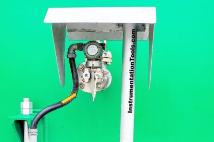
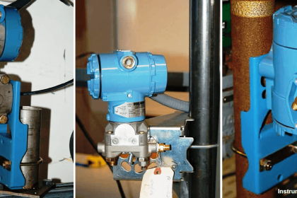
Another common source of trouble for pressure-based flowmeters is improper transmitter location.
Here, the type of process fluid flow being measured dictates how the pressure-sensing instrument should be located in relation to the pipe.
For gas and vapor flows, it is important that no stray liquid droplets collect in the impulse lines leading to the transmitter, lest a vertical liquid column begin to collect in those lines and generate an error-producing pressure.
For liquid flows, it is important that no gas bubbles collect in the impulse lines, or else those bubbles may displace liquid from the lines and thereby cause unequal vertical liquid columns, which would (again) generate an error-producing differential pressure.
In order to let gravity do the work of preventing these problems, we must locate the transmitter above the pipe for gas flow applications and below the pipe for liquid flow applications.
Mounting Position for Gas and Liquid Medium
This illustration shows both installations for a horizontal pipe:

Mounting Position on Vertical Pipelines
This next illustration shows both installations on a vertical pipe:

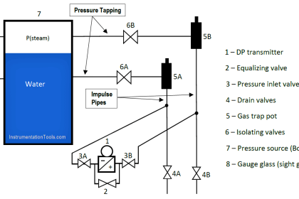
Condensible vapor applications (such as steam flow measurement) have traditionally been treated similarly to liquid measurement applications.
Here, condensed liquid will collect in the transmitter’s impulse lines so long as the impulse lines are cooler than the vapor flowing through the pipe (which is typically the case).
Placing the transmitter below the pipe allows vapors to condense and fill the impulse lines with liquid (condensate), which then acts as a natural seal protecting the transmitter from exposure to hot process vapors.
In such applications it is important for the technician to pre-fill both impulse lines with condensed liquid prior to placing the flowmeter into service.
“Tee” fittings with removable plugs or fill valves are provided to do this. Failure to pre-fill the impulse lines will likely result in measurement errors during initial operation, as condensed vapors will inevitably fill the impulse lines at slightly different rates and cause a difference in vertical liquid column heights within those lines.
It should be noted that some steam flow element installations, however, will work well if the impulse lines are above the pipe.
If such an installation is possible, the advantage of not having to deal with pre-filling impulse lines (or waiting for steam to condense to equal levels in both lines) are significant.
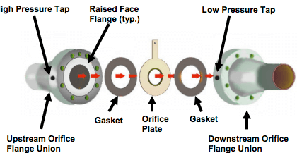
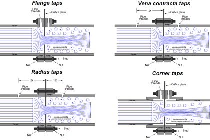
If tap holes must be drilled into the pipe (or flanges) at the process site, great care must be taken to properly drill and de-burr the holes.
A pressure-sensing tap hole should be flush with the inner pipe wall, with no rough edges or burrs to create turbulence.
Also, there should be no reliefs or countersinking near the hole on the inside of the pipe. Even small irregularities at the tap holes may generate surprisingly large flow-measurement errors.
If you liked this article, then please subscribe to our YouTube Channel for Instrumentation, Electrical, PLC, and SCADA video tutorials.
You can also follow us on Facebook and Twitter to receive daily updates.
Read Next:
- Velocity-based Flow Meter
- Swirl Flow Meters Working
- Flow Sensor Rangeability
- Segmental Wedge Flow Meter
- Transit time & Doppler Flow Meter


For not to any pressure drop, the value of distance must be kept after bending the pipeline. Please specify value. Thanks
From what i know, it must be a minimum of 2.5x pipe diameter
flow transmitter can possible to installed down side from the taping point if up side installation is not possible as per site condition.
Dear sir;
Hi.
First , thank you very much . I have said that I use and enjoy reading the valuable content of your site.
Unfortunately , most of illustrations that mentioned in contents in some articles are not shown .
for example : In article “Flow Meter Installation Guidelines”, 4 illustration/images not shown. your help to solve this problem will be so appreciation.
Best Regards
H.Makhlooghi
Is it necessary to have 5D straight length on u/s and D/s of Mechanical flow meters, Can not we fix with straight lengths