Inst ToolsInst ToolsInst Tools
  • Courses
  • Automation
    • PLC
    • Control System
    • Safety System
    • Communication
    • Fire & Gas System
  • Instrumentation
    • Design
    • Pressure
    • Temperature
    • Flow
    • Level
    • Vibration
    • Analyzer
    • Control Valve
    • Switch
    • Calibration
    • Erection & Commissioning
  • Interview
    • Instrumentation
    • Electrical
    • Electronics
    • Practical
  • Q&A
    • Instrumentation
    • Control System
    • Electrical
    • Electronics
    • Analog Electronics
    • Digital Electronics
    • Power Electronics
    • Microprocessor
  • Request
Search
  • Books
  • Software
  • Projects
  • Process
  • Tools
  • Basics
  • Formula
  • Power Plant
  • Root Cause Analysis
  • Electrical Basics
  • Animation
  • Standards
  • 4-20 mA Course
  • Siemens PLC Course
Reading: Turbine Flow Meter Coefficient and Scaling Factor
Share
Notification Show More
Font ResizerAa
Inst ToolsInst Tools
Font ResizerAa
  • Courses
  • Design
  • PLC
  • Interview
  • Control System
Search
  • Courses
  • Automation
    • PLC
    • Control System
    • Safety System
    • Communication
    • Fire & Gas System
  • Instrumentation
    • Design
    • Pressure
    • Temperature
    • Flow
    • Level
    • Vibration
    • Analyzer
    • Control Valve
    • Switch
    • Calibration
    • Erection & Commissioning
  • Interview
    • Instrumentation
    • Electrical
    • Electronics
    • Practical
  • Q&A
    • Instrumentation
    • Control System
    • Electrical
    • Electronics
    • Analog Electronics
    • Digital Electronics
    • Power Electronics
    • Microprocessor
  • Request
Follow US
All rights reserved. Reproduction in whole or in part without written permission is prohibited.
Inst Tools > Blog > Flow Measurement > Turbine Flow Meter Coefficient and Scaling Factor

Turbine Flow Meter Coefficient and Scaling Factor

Turbine flowmeter generates 10 pulses per gallon of liquid passing through it. Determine the meter coefficient and calculate the scaling factor.

Last updated: November 2, 2023 10:01 am
Editorial Staff
Flow Measurement Formulas
No Comments
Share
1 Min Read
SHARE

A digital turbine flowmeter generates 10 pulses per gallon of liquid passing through it.

Determine the meter coefficient and calculate the scaling factor that is needed to develop an output in which each pulse would represent 100 gallons.

Turbine Flow Meter Scaling Factor

Solution:

The meter coefficient is as follows:
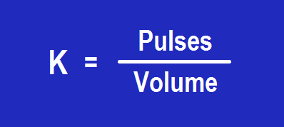
Turbine Flow meter coefficient

K = Pulses / Volume

so as per above inputs, K = 10 Pulses / gallon

The scaling factor is as follows:

 = (10 pulses/gallon) x (100 gallons)

= 1000 pulses

Therefore, a scaling factor of 1,000 is necessary to ensure that the flowmeter’s digital circuit generates one output pulse for every 1,000 pulses generated by the magnetic pickup coil.

If you liked this article, then please subscribe to our YouTube Channel for Instrumentation, Electrical, PLC, and SCADA video tutorials.

You can also follow us on Facebook and Twitter to receive daily updates.

Read Next:

  • Vortex Flow Meter Principle
  • Dall Tube Flow Meter Principle
  • Flow Meter Verification
  • MPFM Working Principle
  • Flow Transmitter Questions
Don't Miss Our Updates
Be the first to get exclusive content straight to your email.
We promise not to spam you. You can unsubscribe at any time.
Invalid email address
You've successfully subscribed !

Continue Reading

Open Channel Flow Measurement Principle
Relationship between Temperature Scales
Thermal Mass Flow Meter – Principle, Advantages, Applications
How to Convert Cable Size from AWG to Inches
Laminar Flow Meter Working Principle
What is Differential Pressure Flow Meter?
Share This Article
Facebook Whatsapp Whatsapp LinkedIn Copy Link
Share
Leave a Comment

Leave a Reply Cancel reply

Your email address will not be published. Required fields are marked *

Stay Connected

128.3kFollowersLike
69.1kFollowersFollow
210kSubscribersSubscribe
38kFollowersFollow

Categories

Explore More

Paddle Wheel Flow Meters – Principle, Advantages, Limitations
Magnetic Flowmeter vs. Turbine Flowmeter – Comparison
What is a Weigh Feeder?
Calculate Flow Transmitter Output Current
What is Integral Flow Orifice Assembly?
Flare Ultrasonic Flow Meter – SOPAS Engineering Tool
Thermal Dispersion Flow Switch Working Principle
Rotameter Working Principle and Animation

Keep Learning

ROTARY ABUTMENT FLOW METERS WORKING ANIMATION

Rotary Abutment Flow Meters Working Principle and Animation

Orifice Flow Measurement Formula

Basics of Flow Measurement

Turbine Meter in Gas Metering System

Read Gas Composition from Gas Metering System using RS485 Protocol

Impulse line - Purpose & Tapping Point Location

Impulse Line – Purpose & Tapping Point Location

multi-hole-restriction-orifice-plate

Basics of Restriction Orifice (RO) – Types, Applications, Standards

magnetic-flow-meter-earthing

Importance of Magnetic Flow Meters Grounding

Gas flow rate Formulas

Gas Flow Formulas

Turbine Meter Custody Transfer

What is Gas Meter and Regulating Station?

Learn More

PLC Program for Car Parking

PLC Program for Entry and Exit Control of Car Parking

PLC Stop - Start Circuit

Introduction to PLC Ladder Diagrams

Tank car bonding at siding

Electrical Static Grounding Techniques

Electromagnetic Noise Interference

What is Electromagnetic Noise Interference?

SCADA backup too has been configured

FactoryTalk Studio and SQL Server for Data Logging

Functions of Pressure Detectors

Functions of Pressure Detectors

liquid level Measurement

Hydrostatic Level Measurement – Temperature related Density Change Effects

Shutdown Maintenance

The 5 Phases of Conducting Shutdown Maintenance

Menu

  • About
  • Privacy Policy
  • Copyright

Quick Links

  • Learn PLC
  • Helping Hand
  • Part Time Job

YouTube Subscribe

Follow US
All rights reserved. Reproduction in whole or in part without written permission is prohibited.
Welcome Back!

Sign in to your account

Username or Email Address
Password

Lost your password?