Inst ToolsInst ToolsInst Tools
  • Courses
  • Automation
    • PLC
    • Control System
    • Safety System
    • Communication
    • Fire & Gas System
  • Instrumentation
    • Design
    • Pressure
    • Temperature
    • Flow
    • Level
    • Vibration
    • Analyzer
    • Control Valve
    • Switch
    • Calibration
    • Erection & Commissioning
  • Interview
    • Instrumentation
    • Electrical
    • Electronics
    • Practical
  • Q&A
    • Instrumentation
    • Control System
    • Electrical
    • Electronics
    • Analog Electronics
    • Digital Electronics
    • Power Electronics
    • Microprocessor
  • Request
Search
  • Books
  • Software
  • Projects
  • Process
  • Tools
  • Basics
  • Formula
  • Power Plant
  • Root Cause Analysis
  • Electrical Basics
  • Animation
  • Standards
  • 4-20 mA Course
  • Siemens PLC Course
Reading: Gas Detectors Installation Techniques
Share
Notification Show More
Font ResizerAa
Inst ToolsInst Tools
Font ResizerAa
  • Courses
  • Design
  • PLC
  • Interview
  • Control System
Search
  • Courses
  • Automation
    • PLC
    • Control System
    • Safety System
    • Communication
    • Fire & Gas System
  • Instrumentation
    • Design
    • Pressure
    • Temperature
    • Flow
    • Level
    • Vibration
    • Analyzer
    • Control Valve
    • Switch
    • Calibration
    • Erection & Commissioning
  • Interview
    • Instrumentation
    • Electrical
    • Electronics
    • Practical
  • Q&A
    • Instrumentation
    • Control System
    • Electrical
    • Electronics
    • Analog Electronics
    • Digital Electronics
    • Power Electronics
    • Microprocessor
  • Request
Follow US
All rights reserved. Reproduction in whole or in part without written permission is prohibited.
Inst Tools > Blog > Erection & Commissioning > Gas Detectors Installation Techniques

Gas Detectors Installation Techniques

Last updated: April 22, 2017 4:01 am
Editorial Staff
Erection & Commissioning Fire & Gas System Instrumentation Design
No Comments
Share
5 Min Read
SHARE

When considering the design of a combustible gas detection system, it is important to select the correct product for the purpose intended. It is likely that a combination of point and open-path detection will be appropriate, so it is a good idea to discuss the selection with the chosen manufacturer.

To summarize, an analysis of the risk and equipment selection process will likely include:

  • Potential leak sources
  • Factors affecting rate and direction of gas diffusion when a leak occurs
  • Density and other physical properties of the gas
  • Detector environment, e.g., temperature, vibration, cleanliness, ventilation, etc.

Gas Detectors Placement

The placement of combustible gas detection sensors is dependent upon many factors, which can only be dealt with here in brief.

When approaching a potential combustible hazard situation, there are generally two ways to determine the location of sensors. One way is to place the sensors close to where a leak is most likely to occur. This utilizes gas detection as a maintenance function for leak detection. The second way is to place sensors near areas where a concentration of hazardous gas may accumulate as a result of the diffusion of a leaking gas or vapor. The density of the gas or vapor determines whether it tends to rise or fall, and is a primary factor in determining the number and location of the sensors.

The wiring of sensors in series is often considered for cost reduction purposes, however, such an approach will result in cumulative outputs, difficulty in the calibration of the sensors and a reduction in the degree of safety the sensors can provide. Furthermore, an open circuit in one sensor will result in the loss of output of all other sensors in the series. A preferable approach is to have the sensors independently monitored and powered. The selected output then can be reliably utilized to warn of the presence of gas and to determine its location.

Sensor locations should take due recognition of the manufacturer’s stated temperature limits. Another factor that must be considered in sensor location is the amount of vibration to which the sensor may be exposed. For instance, installation near turbine engines or pumps may result in a vibration level damaging to the sensor. Furthermore, the natural resonant frequency of the sensor must be considered when evaluating the vibration characteristics of the location. The life of a sensor can be shortened significantly if resonance occurs between the sensor and the installation location.

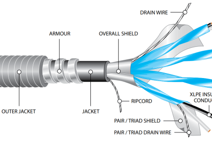
When installing a sensor, proper instrument wiring practices must be observed. The sensor wiring should be separate from AC wiring. Most sensors are not affected by DC wiring, and therefore need not be shielded when mounted in close proximity to other DC applications. Wiring near high powered electric circuits, however, will most likely require shielding. When utilizing shielding, the wire should be grounded only at the controller or receiver end, and the outer braid must not contact the conduit or junction box. It is good engineering to always use shielded cable. Each sensor location should be checked and calibrated on a regular basis, using a calibration gas of known concentration. Typically this should be a 50% LEL mixture of gas or vapor. The frequency of inspection and the need for calibration is best determined by experience with the actual installation. The equipment manufacturer usually suggests intervals depending upon the application in question. In general, infrared detection requires less frequent calibration checks.

Sensors should be located so that they are accessible for calibration. If a sensor is not accessible, regular inspection and necessary calibration is unlikely to be performed. Sensors should be located where they will not be exposed to the possibility of immersion in water. Dust covers may be required for sensors that are located in particularly dirty environments and splashguards in areas where heavy rain is likely or where high-pressure wash-downs are performed. Catalytic sensors should be mounted with the sensor pointing downward while IR sensors should be mounted horizontally.

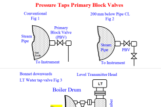
Some Installation Examples :

Gas Detectors Location Installation

Don't Miss Our Updates
Be the first to get exclusive content straight to your email.
We promise not to spam you. You can unsubscribe at any time.
Invalid email address
You've successfully subscribed !

Continue Reading

Package System Architecture – Control & Instrumentation
Differences between No-load Supply Current and Load Current
Infrared Open Path Gas Detectors Working Principle
Ferrules and Cross Ferruling
What is a Mimic Panel ?
Basics of Permissive and Interlock Circuits
Share This Article
Facebook Whatsapp Whatsapp LinkedIn Copy Link
Share
Leave a Comment

Leave a Reply Cancel reply

Your email address will not be published. Required fields are marked *

Stay Connected

128.3kFollowersLike
69.1kFollowersFollow
210kSubscribersSubscribe
38kFollowersFollow

Categories

Explore More

As per Process Conditions, Find out the Circuit Components Status ?
Pressure Switch Terminology
Beam Detectors Working Principle Animation
Chlorine Gas Hazards
Pressure Control Valves vs Pressure Regulators
Active and Passive Fire Protection
Oxygen Safety Analyzer
Transmitter Detailed Specifications

Keep Learning

cross

Tube Fitting Types

Why 4-20mA Standard is so popular

Why 4-20 mA Standard is so popular ?

Cut-outs between Platforms or Grating for Field Instruments

Cut-outs between Platforms or Grating for Field Instruments

Argonite Fire Suppression System Animation

Argonite Fire Suppression System Working Principle

Linear Heat Detector Working Principle

What are Linear Heat Detectors?

Fire and Gas System

Types of Fire and Gas Detectors

Instrumentation Project Documents

List of Instrumentation Project Engineering Documents

Load Cell Design

Load Cell Design

Learn More

PLC FBD Example for Tank Liquid Heating Control by Steam Flow

PLC FBD Example for Tank Liquid Heating Control by Steam Flow

Why Using VoIP Systems

Why Using VoIP Systems Can Save You and Your Business Money?

NDIR gas analysis

Non-Dispersive Analyzers

How to use PLC With SQL Database

How to use PLC with SQL Database? – Basics & Tutorials

Time Response Analysis

Time Response of First Order Systems Objective Questions

Valves Legend P&ID

Comparison of Gate Valves and Globe Valves

Programmable Logic Controller (PLC) Questions and Answers

Programmable Logic Controller (PLC) Questions and Answers – 3

Download a Ladder logic program to GE PLC

Menu

  • About
  • Privacy Policy
  • Copyright

Quick Links

  • Learn PLC
  • Helping Hand
  • Part Time Job

YouTube Subscribe

Follow US
All rights reserved. Reproduction in whole or in part without written permission is prohibited.
Welcome Back!

Sign in to your account

Username or Email Address
Password

Lost your password?