This program is an exercise for the students to learn the PLC timer applications examples on coffee machine programming.
Note: This example program is an exercise for the students to learn the usage of timers.
PLC Timer Practice Exercise
Problem Statement
Design a PLC ladder logic for the following application.
We are using one toggle switch to Dispense Coffee, Water, Milk, and Perform stirring.
The machine should dispense the appropriate amount of Coffee for 5 seconds, then Water for 10 seconds, followed by Milk for 8 seconds. The process should end with a stirring of 5 seconds.
Free PLC Training Video
Our free PLC training video is useful for the students and technicians to master the ladder logic.
Inputs and Outputs
Digital Inputs
Start Button: I0.0
Digital Outputs
Coffee: Q0.0
Water: Q0.1
Milk: Q0.2
Stirring: Q0.3
Coffee Machine Programming
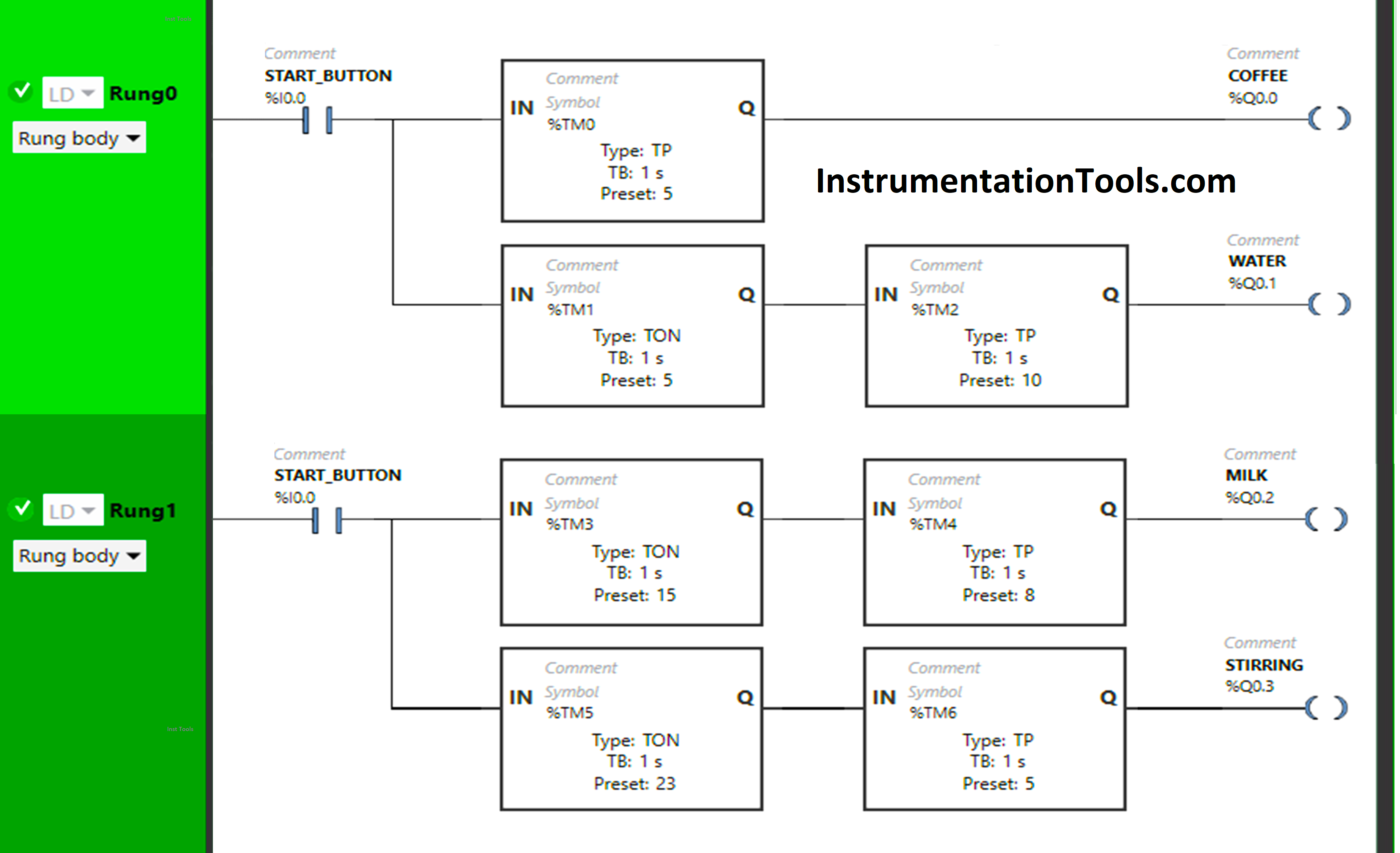
Program Description
We have used Normally Open Contact for the Start Button(I0.0).
In Rung 0:
- Normally Open Contact is used for the Start Button (I0.0) to Turn ON the outputs Coffee (Q0.1) and Water (Q0.1).
- Timer Function Block type TP is used to Turn ON the output Coffee (Q0.0) for a limited time.
- Timer Function Block type TON is used to delay the turning ON time of the output Water (Q0.1) for some time.
- Timer Function Block type TP is used to Turn ON the output Water (Q0.1) for a limited time.
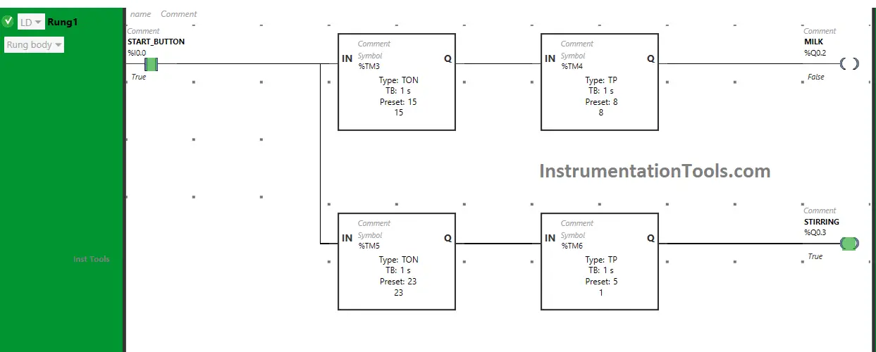
In Rung 1:
- Normally Open Contact is used for the Start Button (I0.0) to Turn ON the outputs Milk (Q0.2) and stirring (Q0.3).
- Timer Function Block type TON timer is used to delay the turning ON time of the output Milk (Q0.2) for some time.
- Timer Function Block type TP is used to Turn ON the output Milk (Q0.2) for a limited time.
- Timer Function Block type TON is used to delay the turning ON time of the output Stirring (Q0.3) for some time.
- Timer Function Block type TP is used to Turn ON the output Stirring (Q0.3) for a limited time.
Logic Simulation
Let’s simulate the PLC program. Here we show the required part of the logic instead of the complete logic. We suggest you watch the above video to learn about this example program.
Rung 0:
When the Start Button (I0.0) is turned ON, the output Coffee (Q0.0) turns ON ( Machine starts dispensing Coffee) but for a limited time as Timer Function type TP is used to turn ON the Output Coffee (Q0.0) or dispense the Coffee for a limited time.
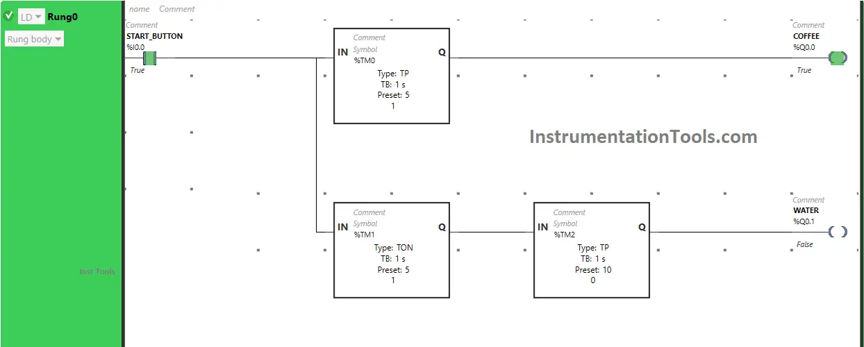
The time is set to 5 seconds. So after 5 seconds, the output Coffee (Q0.0) will turn OFF, or after 5 seconds the dispensing of Coffee finishes.
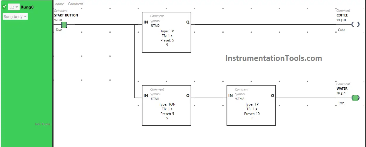
Also, when the Start Button (I0.0) is turned ON, the output Water (Q0.1) will turn ON after 5 seconds or the Machine will start dispensing water after 5 seconds (i.e immediately after the output Coffee(Q0.0) is turned OFF or after the dispensing of coffee is finished) because Timer Function Block TON is used to delay the turning ON time of the output Water (Q0.1).
The time is set to 5 seconds. So after 5 seconds, the output Water (Q0.1) will turn ON, or after 5 seconds Machine starts dispensing water but for a limited time as Timer Function Block type TP is used to turn ON the output Water (Q0.1) for a limited time.
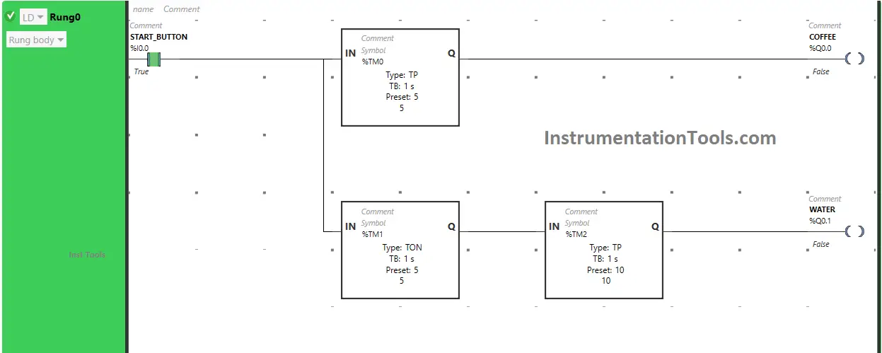
The time is set to 10 seconds. So after 10 seconds, the output Water (Q0.1) turns OFF, or after 10 seconds dispensing of Water finishes.
Rung 1:
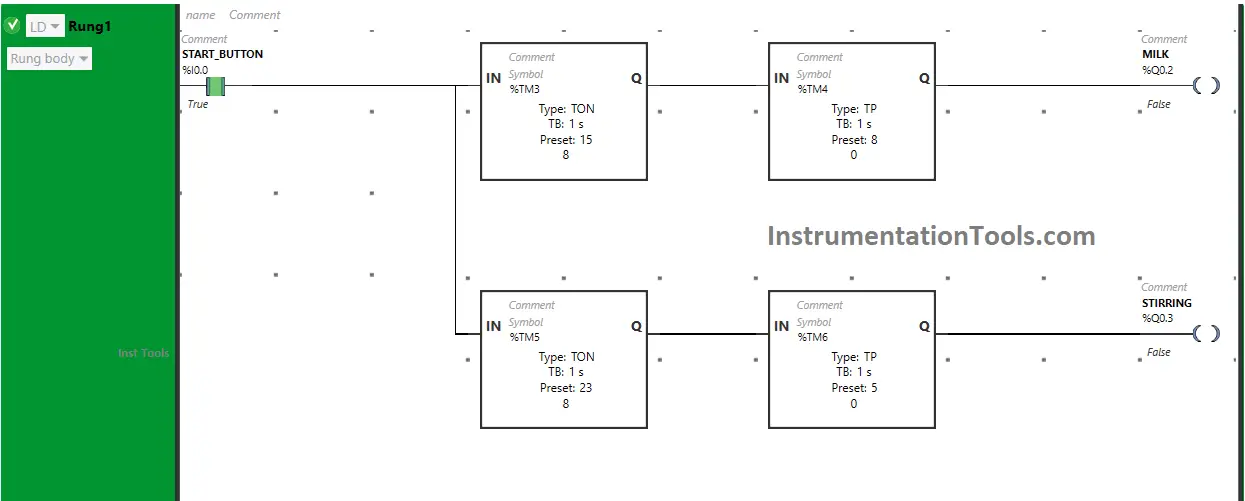
When the Start Button (I0.0) is turned ON, the output Milk (Q0.2) turns ON after 15 seconds, or after 15 seconds Machine starts dispensing Milk (i.e immediately after the output Water (Q0.1) is turned OFF or after the dispensing of Water is finished) because Timer Function Block TON is used to delay the turning ON time of the output Milk (Q0.2).
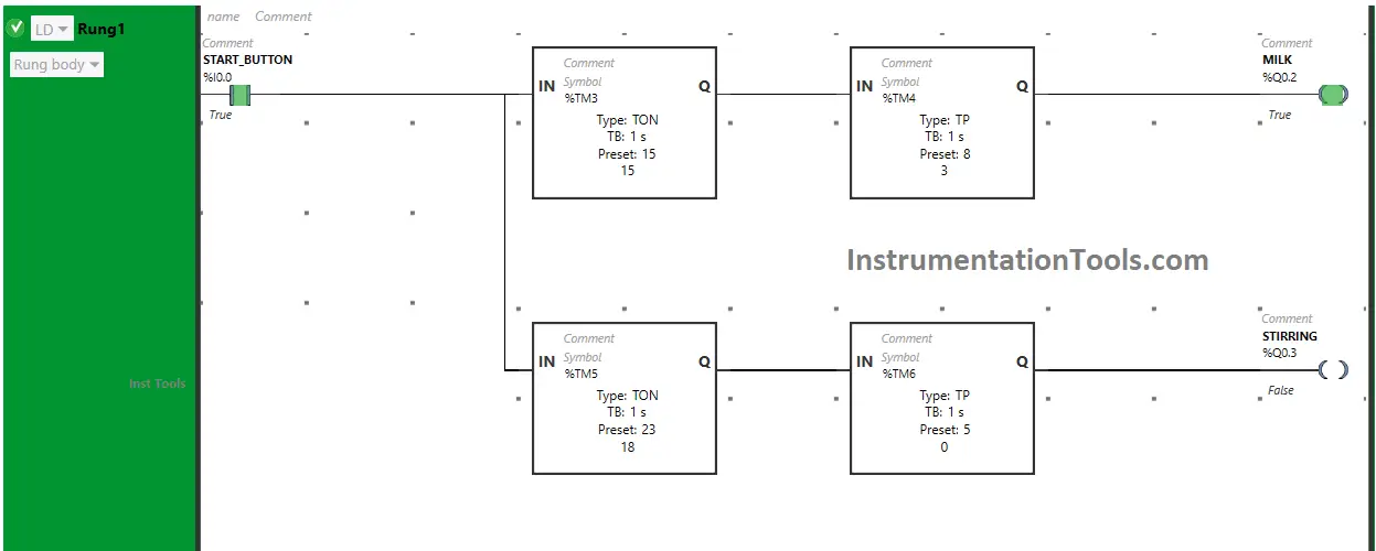
The time is set to 15 seconds. So after 15 seconds, the output Milk (Q0.2) will turn ON, or after 15 seconds Machine will start dispensing Milk but for a limited time as Timer Function Block type TP is used to turn ON the output Milk (Q0.2) for a limited time.
The time is set to 8 seconds. So after 8 seconds, the output Milk (Q0.2) turns OFF, or after 8 seconds dispensing of Milk finishes.
Also, When the Start Button (I0.0) is turned ON, the output Stirring (Q0.3) will turn ON after 23 seconds or after 23 seconds Machine starts Stirring (i.e immediately after the output Milk(Q0.2) is turned OFF or after the dispensing of Milk is finished) because Timer Function Block TON is used to delay the turning ON time of the output Stirring (Q0.3).
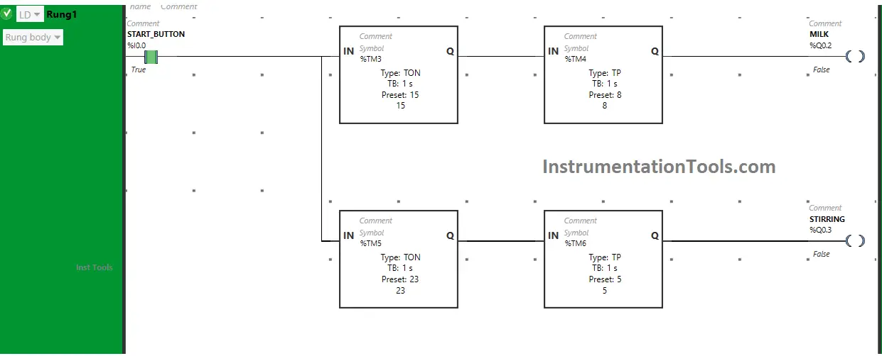
The time is set to 23 seconds. So after 23 seconds, the output Stirring (Q0.3) will turn ON, or after 23 seconds Machine starts Stirring but for a limited time as Timer Function Block type TP is used to turn ON the output Stirring (Q0.3) for a limited time.
The time is set to 5 seconds. So after 5 seconds, the output Stirring (Q0.3) turns OFF, or after 5 seconds stirring finishes.
If you liked this article, please subscribe to our YouTube Channel for PLC and SCADA video tutorials.
You can also follow us on Facebook and Twitter to receive daily updates.
Read Next:
- PLC Program for Entry and Exit Car Parking
- Batch Simulator Program using LogixPro
- Types of Sensors Used in the Dairy Industry
- Pump Run for 10 seconds & OFF for 20 seconds
- Automatic Coffee Vending Machine PLC Logic


Hi,your post is very useful to me for learning the plc program. I’m the beginner stage pls upload the how to learn the plc hardware configuration and how do trouble shooting the problem in plc