This is a PLC Program for Entry/Exit control of the basement or underground car parking.
PLC Car Parking
Problem Description
Due to crowded area we face lots of problems of vehicle parking at basement or underground at shopping mall, hotels, complex etc.
This is happening due to contradiction between the rapidly growing number of vehicles and limited parking spaces in malls, shop and complex in cities results in the phenomenon of “difficult parking and disorderly parking”.
Current parking problem has serious impacts on people’s quality of life and the running of roads.
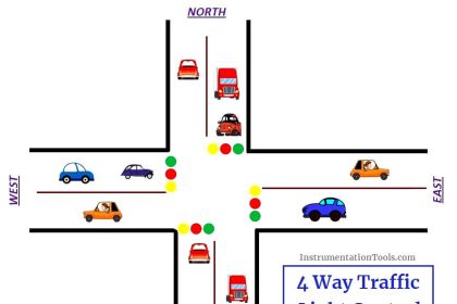
Problem Diagram

Problem Solution
By simple automation we can reduce the car parking problem at basement or underground in shopping mall, hotels, complex etc. The Entry/Exit at basement is a single lane passage and it needs traffic lights to control cars.
Here we consider two lights indication for cars control. Red lights prohibit cars entering or leaving while green lights allow cars entering and leaving.
When car enters at the passage from the entry of the ground floor, both red lights (ground floor and basement) will be ON.
Other car entering and leaving is prohibited during the process till the car passes through the single passage.
When passage is clear both green lights (ground floor and basement) will be ON and allow other cars entering from the ground floor or basement.
Initially we will keep green lights ON and red light OFF
List of Inputs and Outputs
Inputs List
- Main SWITCH : I0.0
- Sensor S1 for ground floor Entry/Exit : I0.1
- Sensor S2 for basement Entry/Exit : I0.2
Outputs List
- Green light (Entry/Exit ground floor) : Q0.0
- Green light (Entry/Exit basement) : Q0.1
- Red light (Entry/Exit ground floor) : Q0.2
- Red light (Entry/Exit basement) : Q0.3
M memory coil List
- M10.0 : Will be ON when car passes sensor S1
- M10.3 : Will be ON when car Passes sensor S2
- M0.0 : Positive edge of system ON
- M0.1 & M11.0 : Positive edge of sensor S1
- M0.3 & M11.1 : Positive edge of sensor S2
- M11.2 : Negative edge of sensor S2
- M11.3 : Negative edge of sensor S1
PLC Ladder Diagram for Entry/Exit control of car parking
Program Description
In this application we have used Siemens S7-300 PLC and TIA Portal Software for programming.
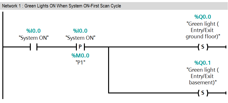
Network 1:
As per above explanation in first network when system is ON (I0.0), initially both green lights (ground floor (Q0.0) and basement (Q0.1)) will be ON. SET instruction is executed and it will set both output Q0.0 and Q0.1.
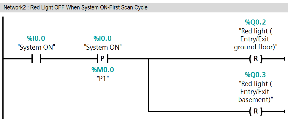
Network 2:
As per above explanation in second network when system is ON (I0.0), initially both red lights (ground floor (Q0.2) and basement (Q0.3)) will be OFF.)
RESET instruction is executed and it will reset both output Q0.2 and Q0.3.
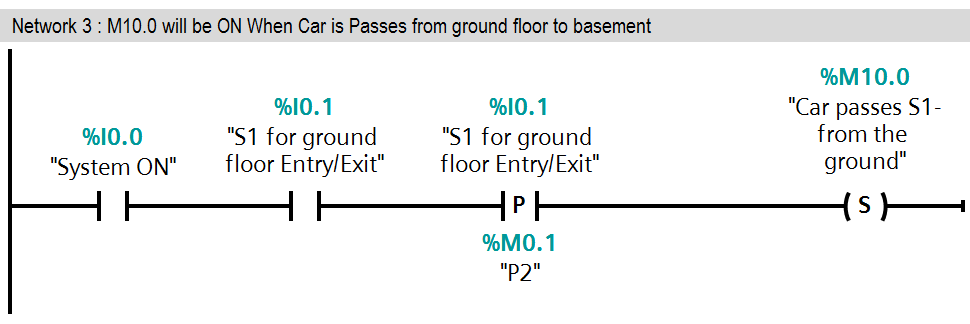
Network 3:
When car enters in the empty passage from the ground floor, sensor S1 (I0.1) will be triggered and with this trigger, memory coil M10.0 will be SET.
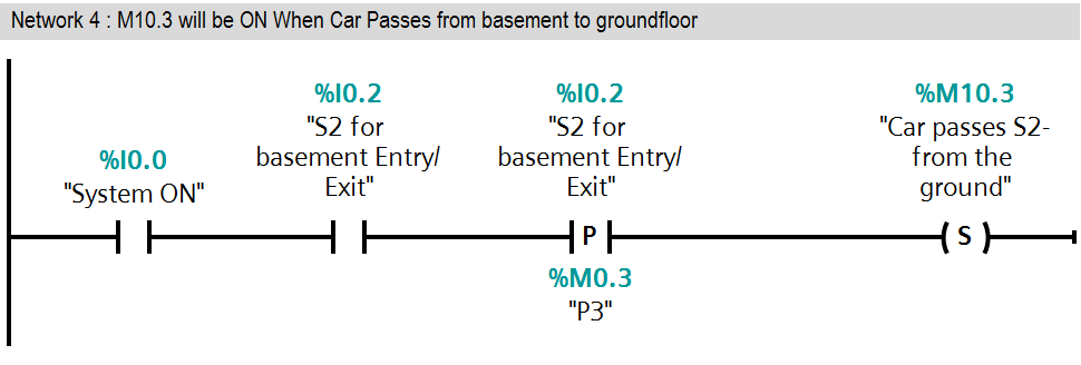
Network 4:
When car enters in the empty passage from the basement, sensor S2 (I0.2) will be triggered and with this trigger, memory coil M10.3 will be SET.
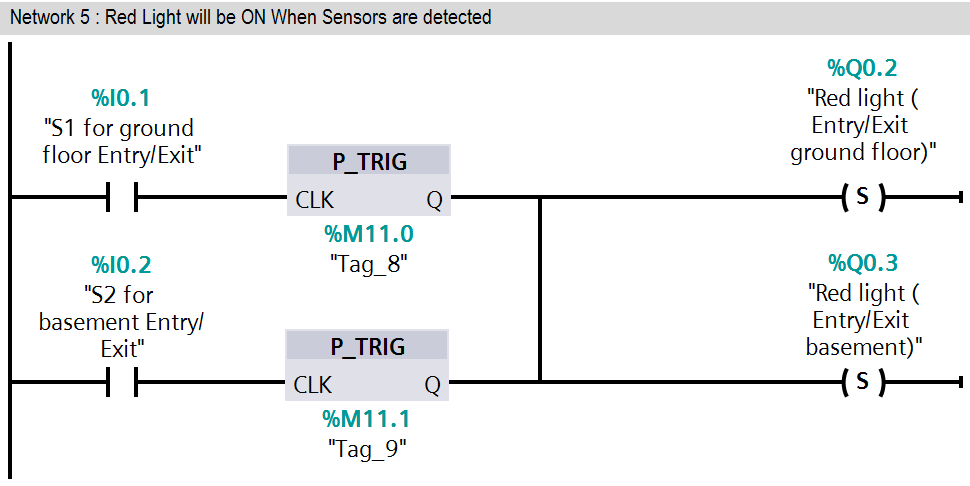
Network 5:
Both red lights will be set by either positive trigger of sensor S1 or sensor S2.
Because when car enters in empty passage then both red lights (Q0.2 & Q0.3) will prohibit car entry/exit from both side.
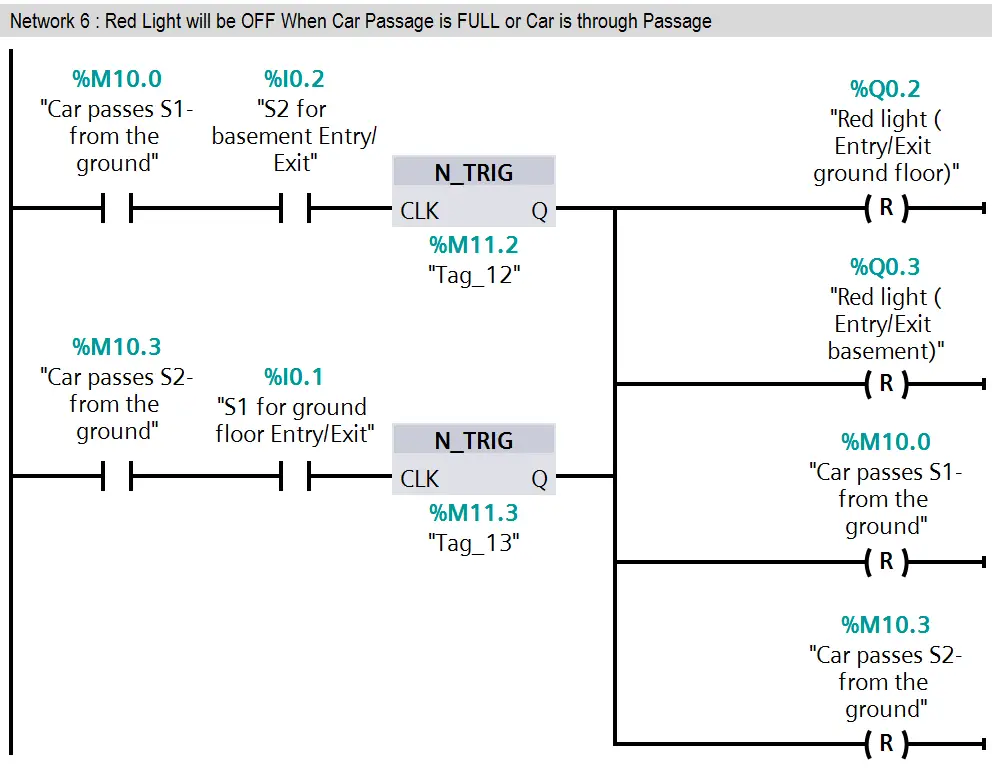
Network 6:
Here we have taken negative trigger of both sensor S1 (I0.1) and S2 (I0.2). so when they triggered red lights (Q0.2 & Q0.3) will be OFF.
When car completely passes empty passage then red lights (Q0.2 & Q0.3) should be OFF.
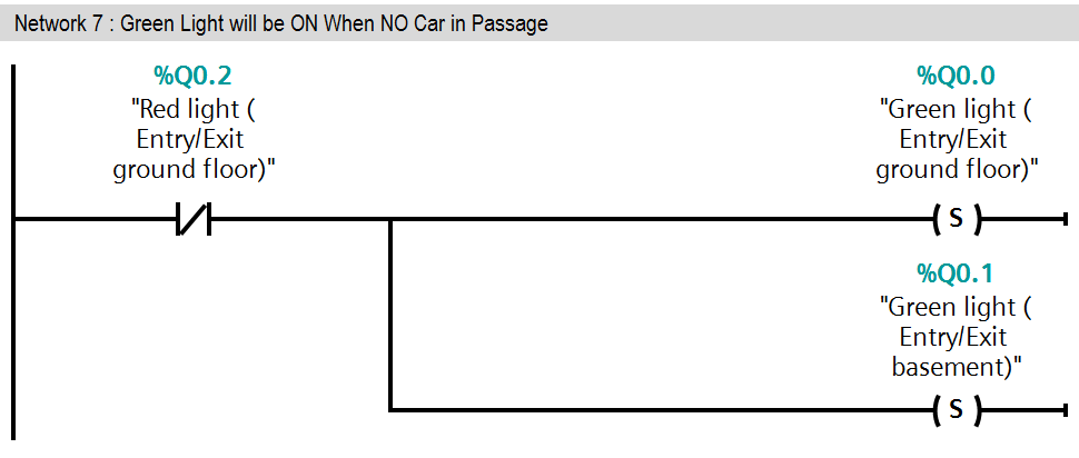
Network 7:
In this network green lights (Q0.0 & Q0.1) will be ON when red lights are OFF.
Green lights (Q0.0 & Q0.1) allow other car for entry or exit.
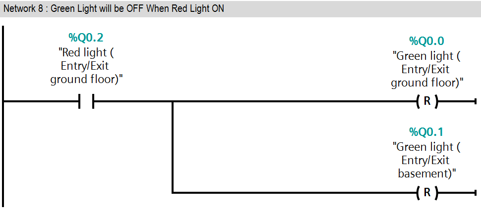
Network 8:
If red lights (Q0.2 & Q0.3) are ON at that time green lights (Q0.0 & Q0.1) should be OFF.
So in this network when red lights (Q0.2 & Q0.3) ON at that time reset instruction will be executed and green lights (Q0.0 & Q0.1) will be OFF
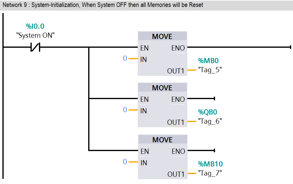
Network 9:
If system ON (I0.0) SWITCH is OFF then all memories should be 0.Here we have taken MOVE instruction for moving zero in all memories (MB0, QB0, and MB10).
This Example is for concept explanation only, not all parameters are considered in this example (such as door open/close system, alarms etc.)
Result

Note : The above PLC Logic provided for basic idea about application of PLC in Car Parking Control of Entry/Exit Gates. The Logic is limited and not complete application.
Author : Bhavesh
If you liked this article, then please subscribe to our YouTube Channel for PLC and SCADA video tutorials.
You can also follow us on Facebook and Twitter to receive daily updates.
Read Next:
- PLC Scaling a Sensor
- Controls Valve using PLC
- PLC Math instructions
- Timer Programming Examples
- Basics of PLC Programming


Thanks a lot
Great