Each team’s system will undergo an inspection simultaneously with the inspection of each team member’s loop diagram.
Contents
Team members will exchange diagrams with each other and then verify from those diagrams what the instructor sees when inspecting each and every panel and connection.
Construction Standards
- All construction must be safe (i.e. must not pose any unnecessary hazard to students or visitors). This includes electrical, chemical, thermal, pressure, and general safety hazards (e.g. trip hazards, cut hazards). Unsafe construction will be dismantled upon discovery.
- All electrical sources greater than 30 volts must be overcurrent-protected and all related wire connections must be guarded against accidental contact (e.g. use recessed terminals with no exposed metal).
- Proper use of colors for electrical power source wiring (e.g. red and black for DC + and −, black and white for AC “hot” and “neutral”, green for earth ground).
- All metallic electrical enclosures must be bonded to earth ground for safety.
- Proper wire types and attachment to terminals (e.g. appropriate wire gauge for the expected current, use of stranded wire wherever possible, correct terminals crimped to ends of wires, no stray wire strands at any point).
- Attached wires must withstand being lightly pulled with fingers.
- Wire insulation must be intact (i.e. no bare wires anywhere).
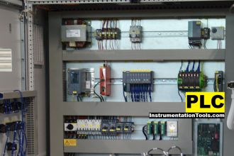
- Panel wiring must be neat in appearance (e.g. all cables run directly from the terminal block to the nearest wire duct, with all excess wire length tucked inside wire duct).
- The wiring outside of panels should be run through conduit wherever possible.
- Correct tools must be used at all times. This includes the use of fixed-size wrenches rather than adjustable wrenches whenever possible, box-end over open-end wrenches whenever possible, and the correct type and size of screwdriver used to turn screw heads.
- All electrical components must be located to avoid exposure to liquids.
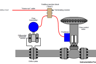
- All tube and pipe connections must be properly made (e.g. correct “swaging” of tube ends, no over-or under-tightened fittings, Teflon tape or pipe sealant used on all NPT threads).
- All manual controls (e.g. buttons, handles, knobs) must be accessible and function without undue effort.
Documentation Standards
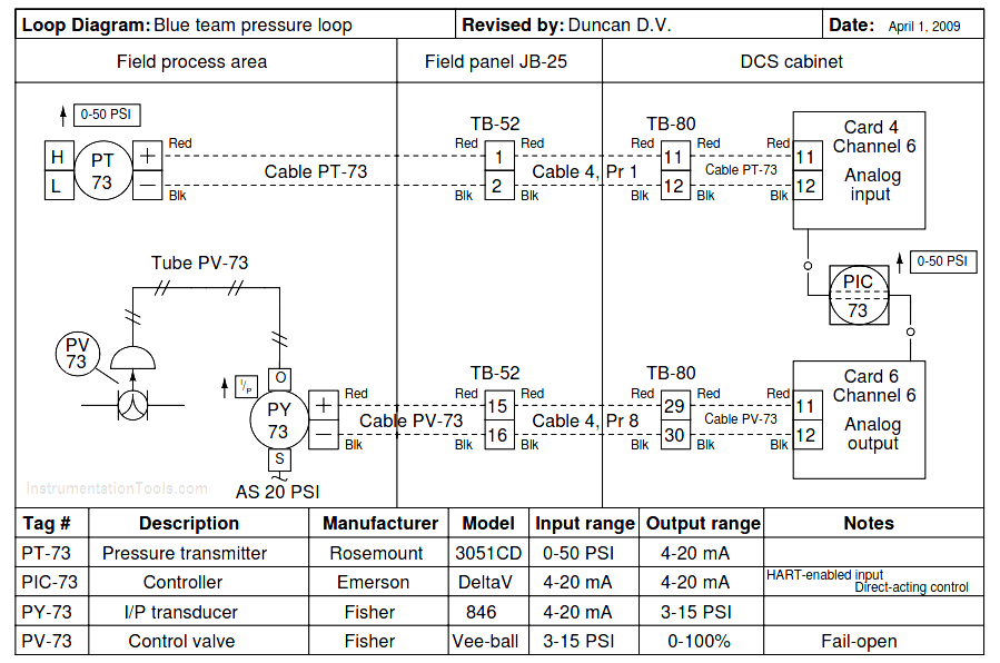
- Loop diagrams must be drawn in accordance with ISA standard 5.1.
- Each instrument must have an appropriate ISA-standard tag name, and this tag name must be visible on the actual instrument (e.g. written on masking tape and attached to the instrument).
- Each signal cable and each signal tube must have an identifying label documented and attached. Long cables must be labeled at each end, as close to the termination points as practical.
- Each team must have its own unique loop number.
- Each instrument’s (final) calibrated range must be shown.
- Each control valve’s fail mode (e.g. fail-open, fail-closed) or action must be shown.
- All writing must be legible (i.e. easy for anyone to read). Hint: large-format paper helps!
- All instrument symbols must be appropriate to the device, function, and location. The large white-colored control panel and the DCS operator stations constitute the main control room. All electrical enclosures in the lab room are auxiliary locations, and everything else is considered a field location.
- Instrument functions shared within a common device must be represented by the “shared” symbol on the diagram (e.g. a controller that is part of a multi-loop control system such as a DCS). Shared controllers must have their identifying loop noted on the diagram (e.g. DCS Loop).
- Any controller I/O cards must be labeled with slot number and channel number in addition to terminal numbers.
- Each location (e.g. field, junction box, control room) must be clearly delineated with vertical separation lines on the diagram.
- Each diagram must be sufficiently detailed so that no other student will have difficulty locating components (e.g. “Where is the controller for this loop?”) or determining important configuration parameters (e.g. range settings).
Common Mistakes
- Incorrect tag name format, using letters that do not conform to the ISA 5.1 standard (e.g. including “PLC” or “DCS” in a controller’s tag name).
- Forgetting that every instrument’s tag name in a loop must begin with the same letter and that this first letter represents the process variable being measured/controlled.
- Forgetting to label all field instruments with their own tag names (e.g. AT-83).
- Failing to label termination points (e.g. terminal block screws) exactly as they are labeled in real life.
- Poor use of space on the diagram paper, causing some portions of the diagram to become “crowded” rather than all components being evenly spaced. Hint: begin your diagram by sketching the field instrument at the far left of the paper and the control room instrument at the far right of the paper, then draw all other instruments and connections in between!
- Forgetting to label all signal wires (see example loop diagrams).
- Forgetting to note all wire colors.
- Forgetting to put your name on the loop diagram!
- Leaving junction box cables outside of wire duct, looking messy.
- Leaving wire duct covers off.
- Basing your diagram off of a team-mate’s diagram, rather than closely inspecting the system for yourself.
- Not placing loop sheet instruments in the correct orientation (field instruments on the left, control room instruments on the right).
Loop Diagram
Interest to add any further points? Share your answers with us through the below comments section.
Read Next:
- Instrument Hook Up
- Instrument Ranging
- Instrumentation Guide
- Mistakes in Instrumentation
- Documentation & Change Control
Credits: Tony R. Kuphaldt