In this post, we will cover the basic topics on motion controllers.
One of the key sectors where automation works is machine automation. It is the type of sector where the use of machines involves PLC, encoders, servo motors and other motion instruments for providing accurate and precise outputs.
These are basically control elements which affect the overall behavior of the machine.
Motion Controllers
Let us simplify machine automation by considering a simple example of cutting machine.
Refer the below image.
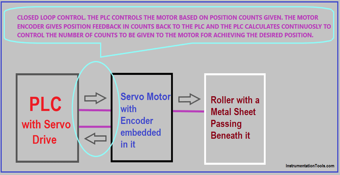
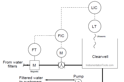
The PLC is the main controller which is ensuring the accurate performance of the machine. You can say it is the heart of the system. It is driving a servo motor through a servo drive; the motor is attached to a gearbox and then it is rotating a roller. A metal sheet is passing beneath the roller.
The servo motor has an encoder embedded in it for position feedback. The role of the PLC is to precisely pass the required length and then, as length is achieved, it will instantly stop the motor (roller here) at that position. The cutting section ahead will cut the length of metal and will start the motion again after cutting has been done. The cycle repeats.
What is interesting here to see is that the system uses closed loop monitoring for control. Closed loop monitoring means the controller (PLC) sends command to an output device (servo motor) and at the same time monitors it’s actual feedback.
The feedback is position here in this example. Based on mathematical calculations written inside the PLC (based on output pulses given and input pulses received from encoder), the servo motor will be controlled accordingly to achieve the set length.
Now, everything is proper here. We will go ahead on why we should a motion controller instead of a PLC. One demerit here in using a PLC is that; the programmer has to manually write many instructions for control. No doubt, servo motor will accurately control the roller motion.
But, factors like scan time in a PLC play an important role in this type of automation. Scan time is the amount of time that a PLC takes to execute a set of instructions, update IO status and communication. In worst case, if any lag occurs in scan time, then the servo motor will stop at a late position instead of the desired position.
This hampers the performance of the system, which now brings motion controller into picture. We will also further see some other features of this controller which could have handled this system more accurately.
A motion controller is nothing but a type of PLC. They have many advanced features as compared to a standard PLC for controlling the motion of an element. This makes it perfect for use in machine automation.
A motion controller is always used in closed loop control; though it has an option to run in open loop control. But, closed loop control is preferred because it takes feedback signal from the instrument and takes corrective action to bring the output (desired position) and the input (actual position) in synchronization with each other; with no faults and errors.
Now, let us consider some features in it
Profile Selection and Design
Profiles are nothing but trajectories or paths. A motion controller allows us to design a path according to our requirement, which the motor will follow at a desired speed and time.
It is a sequence of position commands versus time. This will instruct the motor on where to position itself for the load and how fast it must do it to achieve that position.
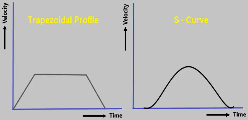
In other terms, it can be said as an acceleration/deceleration chart. When the motor follows this chart, it becomes easier for it to reach the target at a controlled speed and time.
There are many types of profiles such as trapezoidal, s-curve, advanced s-curve, ramp, triangular etc. Each one of them has it’s own application and requirement where it is desired.
The common word used for profiles is CAM control.
Interpolation
Interpolation is defined as the type of motion of the motors, which when synchronized with each other, will create a shape that will be maintained during the whole operation. Their movements need to be co-ordinated with each other and each motion will be defined as an axis.
For example, if 8 motors are used in an application, then it will be an 8-axes controlled motion. In general, there are two types of interpolation used – linear and circular.
When two or more motors are moved in conjunction in a linear fashion, a line would be created between the motors. When two or motors are moved in conjunction in a non-linear fashion, a circle would be created between the motors.
Suppose two motors have to move for linear interpolation. The path is decided for them to move in synchronization with each other. Both of them will mostly move at a same speed to create a line.
For circular interpolation, motors will not move at same speed. They will mostly slow or ramp respectively to create a circle. You can imagine this motion in your mind to get a common sense of the motion.
Now, there will be two types of selection for the controllers used. If a controller supports only single axis and there are two motors, then two motion controllers will be required.
They will communicate with each other regarding the relative position of the corresponding motor, to ensure that interpolation is performed. If a controller supports multiple axes with interpolation, then both the motors will be configured in the same controller and the desired motion can thus be achieved.
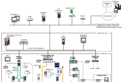
Refer the above image. If two motors work in tandem with each other to take an object to the end position, they would create an interpolation. If there is no interpolation, then see the purple line. The x-axis motor will move first and then after reaching it’s position, it would stop and the y-axis motor will then move to reach the object to it’s desired target.
There are even more complex types of interpolation like continuous trajectory control, helical interpolation, position follow-up control, high-speed oscillation control etc.
Brief Details
There are some special notes which can be considered for motion controllers:
- There are many dedicated function blocks and advanced settings inside the user program to help the programmer achieve a perfect motion. It requires a detailed knowledge of the motion principle.
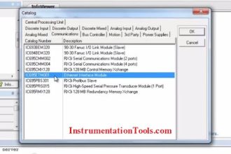
- Most of the controllers have all the communication protocols embedded in it, so that it can talk with all types of devices for dedicated control. The protocols mostly used are Modbus, Ethernet, Profibus, Profinet, CAN Open, Sercos III, EtherCAT etc.
- As a large amount of processing is involved in CPU, they typically use digital signal processors (DSP) for executing the task. They perform mathematical operations and algorithms very quickly.
- Mostly, all the controllers can control upto 32 axes.
Author: Viral Nagda
If you liked this article, then please subscribe to our YouTube Channel for Instrumentation, Electrical, PLC and SCADA video tutorials.
You can also follow us on Facebook and Twitter to receive daily updates.
Read Next: