Inst ToolsInst ToolsInst Tools
  • Courses
  • Automation
    • PLC
    • Control System
    • Safety System
    • Communication
    • Fire & Gas System
  • Instrumentation
    • Design
    • Pressure
    • Temperature
    • Flow
    • Level
    • Vibration
    • Analyzer
    • Control Valve
    • Switch
    • Calibration
    • Erection & Commissioning
  • Interview
    • Instrumentation
    • Electrical
    • Electronics
    • Practical
  • Q&A
    • Instrumentation
    • Control System
    • Electrical
    • Electronics
    • Analog Electronics
    • Digital Electronics
    • Power Electronics
    • Microprocessor
  • Request
Search
  • Books
  • Software
  • Projects
  • Process
  • Tools
  • Basics
  • Formula
  • Power Plant
  • Root Cause Analysis
  • Electrical Basics
  • Animation
  • Standards
  • 4-20 mA Course
  • Siemens PLC Course
Reading: What is a Weigh Feeder?
Share
Notification Show More
Font ResizerAa
Inst ToolsInst Tools
Font ResizerAa
  • Courses
  • Design
  • PLC
  • Interview
  • Control System
Search
  • Courses
  • Automation
    • PLC
    • Control System
    • Safety System
    • Communication
    • Fire & Gas System
  • Instrumentation
    • Design
    • Pressure
    • Temperature
    • Flow
    • Level
    • Vibration
    • Analyzer
    • Control Valve
    • Switch
    • Calibration
    • Erection & Commissioning
  • Interview
    • Instrumentation
    • Electrical
    • Electronics
    • Practical
  • Q&A
    • Instrumentation
    • Control System
    • Electrical
    • Electronics
    • Analog Electronics
    • Digital Electronics
    • Power Electronics
    • Microprocessor
  • Request
Follow US
All rights reserved. Reproduction in whole or in part without written permission is prohibited.
Inst Tools > Blog > Flow Measurement > What is a Weigh Feeder?

What is a Weigh Feeder?

Most common weigh feeder design consists of a conveyor belt with a section supported by rollers coupled to one or more load cells.

Last updated: November 2, 2023 6:34 am
Editorial Staff
Flow Measurement
3 Comments
Share
4 Min Read
SHARE

A special type of flow meter suited for powdered or granular solids is the weigh feeder.

One of the most common weigh feeder designs consists of a conveyor belt with a section supported by rollers coupled to one or more load cells, such that a fixed length of the belt is continuously weighed:

Weigh Feeder
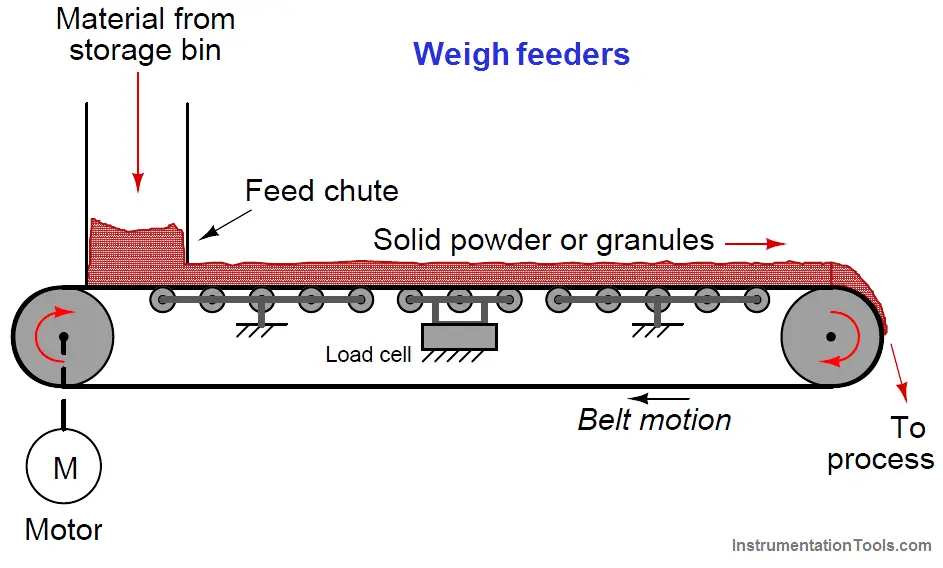
Weigh feeder Principle

The load cell measures the weight of a fixed-length belt section, yielding a figure of material weight per linear distance on the belt.

A tachometer (speed sensor) measures the speed of the belt. The product of these two variables is the mass flow rate of solid material “through” the weigh feeder:

Weigh feeders formula

Where,
W = Mass flow rate (e.g. pounds per second)
F = Force of gravity acting on the weighed belt section (e.g. pounds)
v = Belt speed (e.g. feet per second)
d = Length of weighed belt section (e.g. feet)

A small weigh feeder (about two feet in length) is shown in the following photograph, the weigh feeder being used to feed powdered soda ash into water at a municipal filtration plant to neutralize pH:
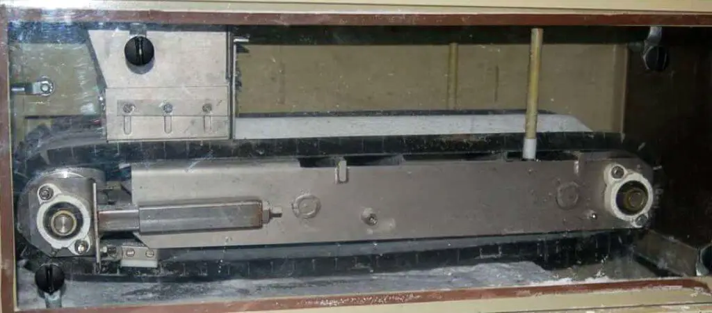
Weigh feeder

In the middle of the belt’s span (hidden from view) is a set of rollers supporting the weight of the belt and of the soda ash piled on the belt. This load cell array provides a measurement of pounds material per foot of belt length (lb/ft).

As you can see in this next picture, the soda ash powder simply falls off the far end of the conveyor belt, into the water below:
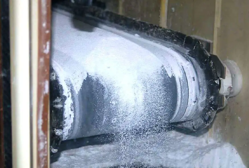
Weigh feeder belt

The speed sensor measures belt speed in feet per minute (ft/min). This measurement, when multiplied by the pounds-per-foot measurement sensed by the load cells, translates into a mass flow rate (W) in units of pounds per minute (lb/min). A simple unit conversion (×60) expresses the mass flow rate in units of pounds per hour (lb/h).

A photograph of this weigh feeder’s display screen shows these variables:
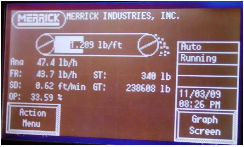
Weigh feeder display

Note that the belt loading of 1.209 lb/ft and the belt speed of 0.62 feet per minute do not exactly equate to the displayed mass flow rate of 43.7 lb/h.

The reason for this discrepancy is that the camera’s snapshot of the weigh feeder display screen happened to capture an image where the values were not simultaneous. Weigh feeders often exhibit fluctuations in belt loading during normal operation, leading to fluctuations in calculated mass flow rate.

Sometimes these fluctuations in measured and calculated variables do not coincide on the display screen, given the latency inherent to the mass flow calculation (delaying the flow rate value until after the belt loading has been measured and displayed).

If you liked this article, then please subscribe to our YouTube Channel for Instrumentation, Electrical, PLC, and SCADA video tutorials.

You can also follow us on Facebook and Twitter to receive daily updates.

Read Next:
  • Load Cell Principle
  • Coriolis Mass meter
  • Conveyor using PLC
  • Load Cell Checks
  • Mass Flow Meters
Don't Miss Our Updates
Be the first to get exclusive content straight to your email.
We promise not to spam you. You can unsubscribe at any time.
Invalid email address
You've successfully subscribed !

Continue Reading

Pressure based Flow Meters
Types of Variable Area Flow Meters
Oval Gear Meter – Principle, Advantages, Limitations, Applications
Transit Time Flow Meter – Types, Advantages, Disadvantages
What is an Orifice Meter?
Dall Tube Flow Meter – Principle, Advantages, Disadvantages
Share This Article
Facebook Whatsapp Whatsapp LinkedIn Copy Link
Share
3 Comments
  • Eswarateja says:
    July 29, 2018 at 3:23 pm

    Nice

    Reply
  • R.Sridhar says:
    December 15, 2021 at 8:41 pm

    Very fine easy to understand.

    Reply
  • Adnan khan says:
    September 7, 2023 at 12:38 pm

    How can calculate the load cell capacity according to the design capacity of feeder

    Reply

Leave a Reply Cancel reply

Your email address will not be published. Required fields are marked *

Stay Connected

128.3kFollowersLike
69.1kFollowersFollow
210kSubscribersSubscribe
38kFollowersFollow

Categories

Explore More

Why is Orifice Beta in between 0.3 to 0.7?
Flow Instruments – Selection, Principle & Application
Design Considerations of Orifice Plate
Mass Flow Meters
Metal Tube Variable Area Flow Meters Principle
Hot Wire Anemometer Principle and Types
Thermal Dispersion Flow Switch Working Principle
Basics of Flow Measurement

Keep Learning

orifice plate vent hole

What is the Purpose of Orifice Plate Drain Hole and Vent Hole?

Orifice Construction

How does an Orifice Measures Flow?

Turbine Flow Meter Installation Procedure

flow Nozzle

Flow Nozzle Principle, Advantages, Disadvantages, Applications

Orifice plate with vent and drain holes

Basics of Orifice Plates

Turbine Flow Meter Calibration

How to do Turbine Flow Meter Verification?

Bernoulli's Principle and Flow Meters

Top Questions on Bernoulli’s Principle in Flow Meters

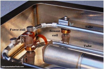
Coriolis flow meter sensor coils

Coriolis Flow Meter Construction

Learn More

State Variable Analysis and Design

Pole Placement by State Feedback

PLC Ladder Logic Simulator Mobile Apps For Android

PLC Ladder Logic Simulator Mobile Apps For Android

Current Earth Leakage Circuit Breaker

Types of Earth Leakage Circuit Breaker

Electrification in Mining Industry

Electrification in Mining Industry

Lithium-ion Battery Charging System

Lithium-ion Battery Charging Systems

Temperature Gauges and Elements Specifications

Temperature Gauges and Elements : Detailed Specifications

SIS Failures and Reliability - Safety Instrumented Systems

SIS Failures and Reliability – Safety Instrumented Systems

Pull Cord Switch Principle

Pull Cord Switch Working Principle

Menu

  • About
  • Privacy Policy
  • Copyright

Quick Links

  • Learn PLC
  • Helping Hand
  • Part Time Job

YouTube Subscribe

Follow US
All rights reserved. Reproduction in whole or in part without written permission is prohibited.
Welcome Back!

Sign in to your account

Username or Email Address
Password

Lost your password?